2.1 Analog Input Unit (FP0R-AD4/AD8)
2-3
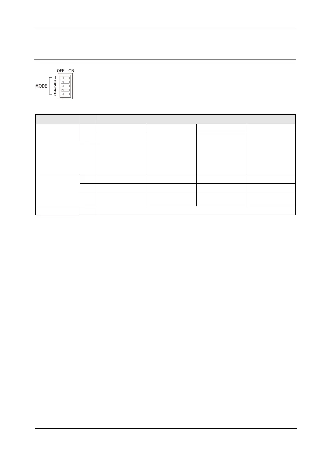
2.1.2 Setting of Mode Switch
Setting of the mode switch
Resolution
and FP0-A21-
compatible
12-bit mode
input range
1 OFF ON OFF ON
FP0-A80-
compatible
12-bit mode
0 to 5V/0 to 20mA
(Note 1)
FP0-A80-
compatible
12-bit mode
-10 to +10V
FP0-A80-
compatible
12-bit mode
-100 to +100mV
(Note 2)
14-bit mode
(Note 3)
The number
of converted
CH
3 OFF ON OFF ON
4 OFF OFF ON ON
2ch
(CH0-CH1)
4ch
(CH0-CH3)
6ch
(CH0-CH5)
8ch
(CH0-CH7)
Input averaging 5 OFF: Averaging Not performed, ON: Averaging Performed
(Note 1): When the both switch No.1 and No.2 are OFF, the voltage/current is switched by the connection method.
(Note 2): This has been implemented in version 1.2 or later. In version 1.1 or earlier, this is reserved for the system
(not available).
(Note 3): In the 14-bit mode, the input range is set by writing into the operation memory WY with a user program.
(Note 4): All the switches are set to OFF at the factory.
(Note 5): The switch settings will be valid when the power is turned ON from OFF. The settings will not change if the
operation power supply is switched when it is ON.

 Loading...


