EasyManuals Logo

Panasonic FP0R Series User Manual

Panasonic FP0R Series
92 pages
To Next Page IconTo Next Page
To Previous Page IconTo Previous Page
Page #24 background imageLoading...
Page #24 background image
Wiring
3-8
3.4 Common Precautions
3.4.1 Wiring of Analog I/O Unit
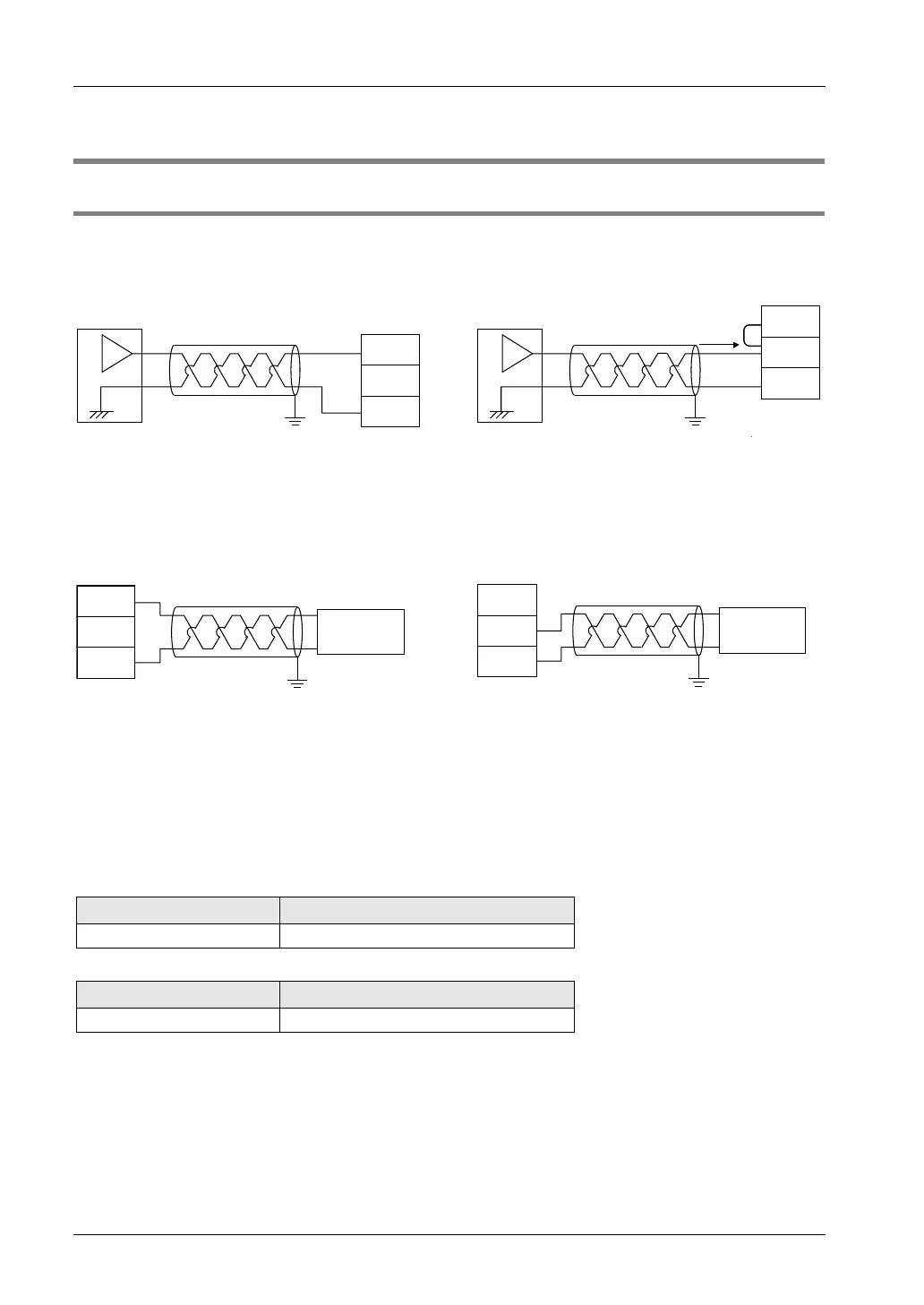
Wiring diagram
Voltage input
Current input
V
COM
I
Analog device
V
COM
I
Analog device
*1
*1: For the current input, short-circuit the V and I terminals.
Voltage output Current output
Analog device Analog device
V
COM
I
V
COM
I
Precautions on Wiring
Use double-core twisted-pair shielded wires. It is recommended to ground the shielding.
However, depending on the conditions of the external noise, it may be better not to ground
the shielding.
Do not have the analog input wiring close to AC wires, power wires, or load wires.
Do not have the analog output wiring close to AC wires, power wires, or load wires.
Compatible cable (twisted wire)
Size
Nominal cross section area
AWG#28-16 0.08 mm
2
-1.25 mm
2
Special tools
Manufacturer
Serial number (model number)
Phoenix Contact Co. SZS0.4×2.5(1205037)

Table of Contents

Questions and Answers:

Question and Answer IconNeed help?

Do you have a question about the Panasonic FP0R Series and is the answer not in the manual?

Panasonic FP0R Series Specifications

General IconGeneral
ModelFP0R Series
ExpansionUp to 3 expansion units
TypeProgrammable Controller
Processing Speed0.08 µs/step
Communication PortsRS232C, RS485
Power Supply24 V DC
Operating Temperature0°C to 55°C
I/O PointsUp to 128 points
CPU Type32-bit RISC
Program MemoryFlash ROM
Dimensions90mm x 60mm x 25mm (varies by model)

Related product manuals