EasyManuals Logo

Panasonic FP0R Series User Manual

Panasonic FP0R Series
92 pages
To Next Page IconTo Next Page
To Previous Page IconTo Previous Page
Page #19 background imageLoading...
Page #19 background image
3.1 Analog Input Unit (FP0R-AD4/AD8)
3-3
3.1.2 Wiring of Analog Input Unit
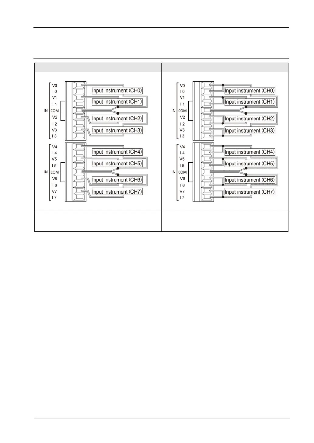
Voltage input Current input
Connect input instrument between V and COM
terminal.
First, connect both V terminal and I terminal.
And then connect input instrument between it and
COM terminal.
(Note 1): Two COM terminals are connected internally.
(Note 2): Two cables or less must be inserted to COM terminal as above (two channel once combined).
(Note 3): Recommend using the twisted and shielded communication cables for analog lines and grounding the end
of shield.

Table of Contents

Questions and Answers:

Question and Answer IconNeed help?

Do you have a question about the Panasonic FP0R Series and is the answer not in the manual?

Panasonic FP0R Series Specifications

General IconGeneral
ModelFP0R Series
ExpansionUp to 3 expansion units
TypeProgrammable Controller
Processing Speed0.08 µs/step
Communication PortsRS232C, RS485
Power Supply24 V DC
Operating Temperature0°C to 55°C
I/O PointsUp to 128 points
CPU Type32-bit RISC
Program MemoryFlash ROM
Dimensions90mm x 60mm x 25mm (varies by model)

Related product manuals