EasyManuals Logo

Panasonic FP0R Series User Manual

Panasonic FP0R Series
92 pages
To Next Page IconTo Next Page
To Previous Page IconTo Previous Page
Page #68 background imageLoading...
Page #68 background image
Creating Programs
4-42
4.5.4 Output conversion Characteristics (Current Range)
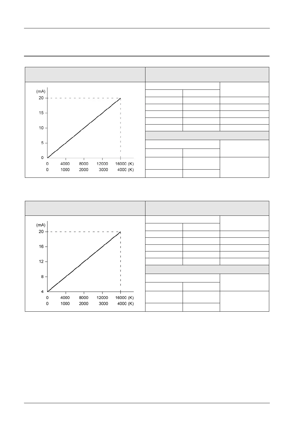
0mA to 20mA output
Conversion characteristic Correspondence table of D/A Conversion
values
Digital value
Output current (mA)
12-bit 14-bit
0
0
0.0
1000
4000
5.0
2000
8000
10.0
3000
12000
15.0
4000
16000
20.0
Processing if the range is exceeded
Digital value
Output current (mA)
12-bit 14-bit
Including
negative value
Including
negative value
Refer to the notes
on the next page.
4001 or more 16001 or more
(Note):For the 12-bit mode, the values for FP0R-A21/A42 are shown. For FP0R-DA4 (12-bit mode), the range is 4 mA
to 20 mA.
4mA to 20mA output
Conversion characteristic
Correspondence table of D/A Conversion
values
Digital value
Output current (mA)
12-bit
14-bit
0
0
4.0
1000
4000
8.0
2000
8000
12.0
3000
12000
16.0
4000
16000
20.0
Processing if the range is exceeded
Digital value
Output current (mA)
12-bit 14-bit
Including
negative value
Including
negative value
Refer to the notes
on the next page.
4001 or more 16001 or more
(Note):For the 12-bit mode, the values for FP0R-DA4 are shown. For FP0R-A21/A42 (12-bit mode), the range is 0 mA
to 20 mA.

Table of Contents

Questions and Answers:

Question and Answer IconNeed help?

Do you have a question about the Panasonic FP0R Series and is the answer not in the manual?

Panasonic FP0R Series Specifications

General IconGeneral
ModelFP0R Series
ExpansionUp to 3 expansion units
TypeProgrammable Controller
Processing Speed0.08 µs/step
Communication PortsRS232C, RS485
Power Supply24 V DC
Operating Temperature0°C to 55°C
I/O PointsUp to 128 points
CPU Type32-bit RISC
Program MemoryFlash ROM
Dimensions90mm x 60mm x 25mm (varies by model)

Related product manuals