EasyManuals Logo

Panasonic FP0R Series User Manual

Panasonic FP0R Series
92 pages
To Next Page IconTo Next Page
To Previous Page IconTo Previous Page
Page #23 background imageLoading...
Page #23 background image
3.3 Analog I/O Unit (FP0R-A21/A42)
3-7
3.3.2 Wiring of Analog I/O Unit
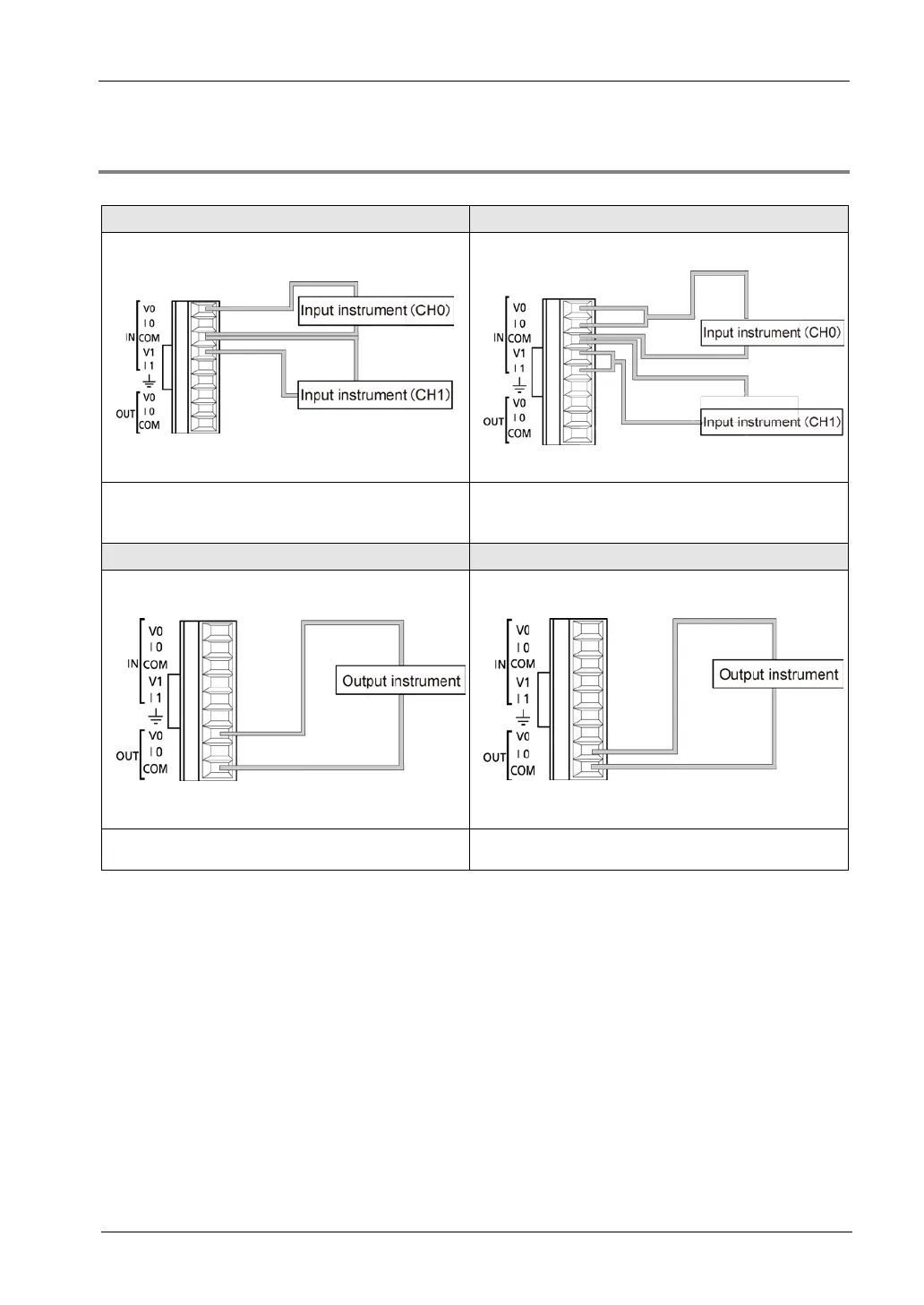
Analog input
Voltage input
Current input
Connect input instrument between IN/V and
IN/COM terminal.
First,connect both IN/V terminal and IN/I terminal.
And then connect input instrument between it and
IN/COM terminal.
Voltage output Current output
Connect output instrument between OUT/V and
OUT/COM terminal.
Connect output instrument between OUT/I and
OUT/COM terminal.
(Note 1):In the above figure, the input (CH0/CH1) and output CH0 are described as representative examples.
The input (CH2/CH3) and output CH1 of A42 type also have the same terminal layouts.
(Note 2): All COM terminals are connected within the unit.

Table of Contents

Questions and Answers:

Question and Answer IconNeed help?

Do you have a question about the Panasonic FP0R Series and is the answer not in the manual?

Panasonic FP0R Series Specifications

General IconGeneral
ModelFP0R Series
ExpansionUp to 3 expansion units
TypeProgrammable Controller
Processing Speed0.08 µs/step
Communication PortsRS232C, RS485
Power Supply24 V DC
Operating Temperature0°C to 55°C
I/O PointsUp to 128 points
CPU Type32-bit RISC
Program MemoryFlash ROM
Dimensions90mm x 60mm x 25mm (varies by model)

Related product manuals