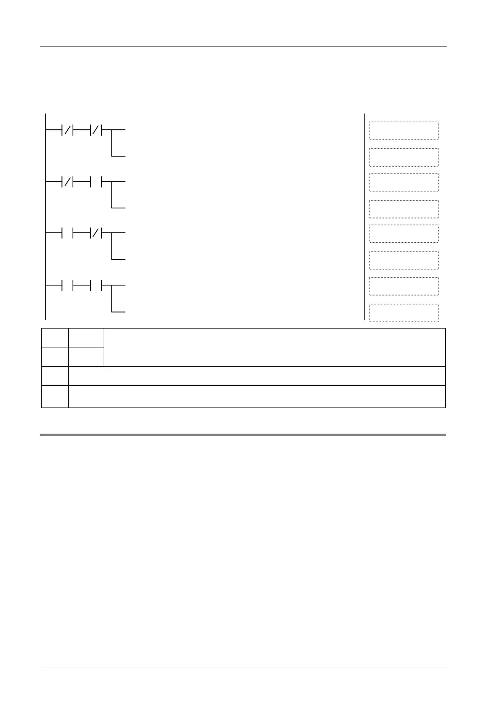
Creating Programs
Sample program (For ranges of 0 to 10 V, 0 to 5 V and 0 to 20 mA)
The following program shows the case that conversion data of the first expansion analog input
unit (CH0 to CH7) is read and stored in DT0 to DT7.
[ F65 WAN
, WX3 , H3FFF , DT3
]
[ F0 MV , WX2 , DT2 ]
X3F
ⓐ
X3E
②①
ⓑ
[ F65 WAN , WX3 , H3FFF , DT1 ]
[ F0 MV , WX2 , DT0 ]
X3F
ⓐ
X3E
②①
ⓑ
[ F65 WAN , WX3 , H3FFF , DT7 ]
[ F0 MV , WX2 , DT6
]
X3F
ⓐ
X3E
②①
ⓑ
[ F65 WAN , WX3 , H3FFF , DT5 ]
[ F0 MV , WX2 , DT4 ]
X3F
ⓐ
X3E
②①
ⓑ
①
X3F
The channels of conversion data read by turning on/off the conversion data switching flags X3F
and X3E are distinguished.
②
X3E
ⓐ
Conversion data of even numbered channels CH0/CH2/CH4/CH6 is transferred as is.
ⓑ
When the data of odd numbered channels CH1/CH3/CH5/HC7 is positive, the most significant two bits
are masked by "00" with F65 WAN (AND) instruction, and the data is stored in DT1/DT3/DT5/DT7.
4.2.2 Setting of Input Range and Averaging Processing (14-bit Mode Only)
When selecting the 14-bit mode in the analog input unit (FP0R-AD4/AD8), the input range and
averaging method can be switched by user programs. They both can be set for each channel.
Default settings
The default settings are as follows; Input range for all channels: -10 to +10 V, Averaging
processing: Moving average processing 10 times (Max. and min. removal). The averaging
processing is enabled when the mode switch No. 5 is ON.

 Loading...


