Wiring
3.3 Analog I/O Unit (FP0R-A21/A42)
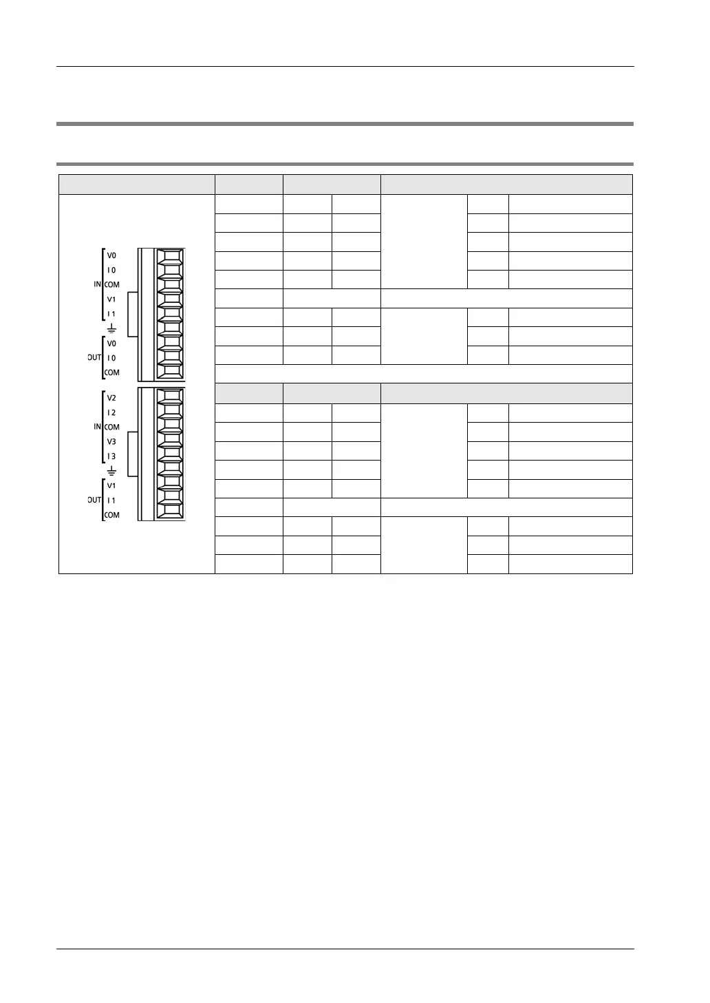
3.3.1 Terminal Layout Diagrams
1 IN V0
Analog input
CH0 Voltage signal input
2 IN I0 CH0 Current signal input
3 IN COM --- Input common
4 IN VI CH1
Voltage signal input
5 IN I1 CH1
Current signal input
6 FG For shield connection of analog signal cable
7 OUT V0
Analog output
CH0 Voltage signal output
8 OUT I0 CH0 Current signal output
9 OUT COM --- Output common
1 IN V0
Analog input
CH2 Voltage signal input
2 IN I0 CH2
Current signal input
3 IN COM ---
Input common
4 IN VI CH3 Voltage signal input
5 IN I1 CH3 Current signal input
6 FG For shield connection of analog signal cable
7 OUT V1
Analog output
CH1 Voltage signal output
8 OUT I1 CH1
Current signal output
9 OUT COM ---
Output common
(Note 1):For inputting a current signal to the analog input part, connect the V terminal and I terminal externally.
(Note 2): All COM terminals are connected within the unit.

 Loading...


