Creating Programs
4.3.2 Writing of Digital Data for Output (14-bit Mode)
With the analog output unit, the conversion output is performed by using two bits as the
switching flags of output channels and writing data.
I/O allocation (14-bit mode)
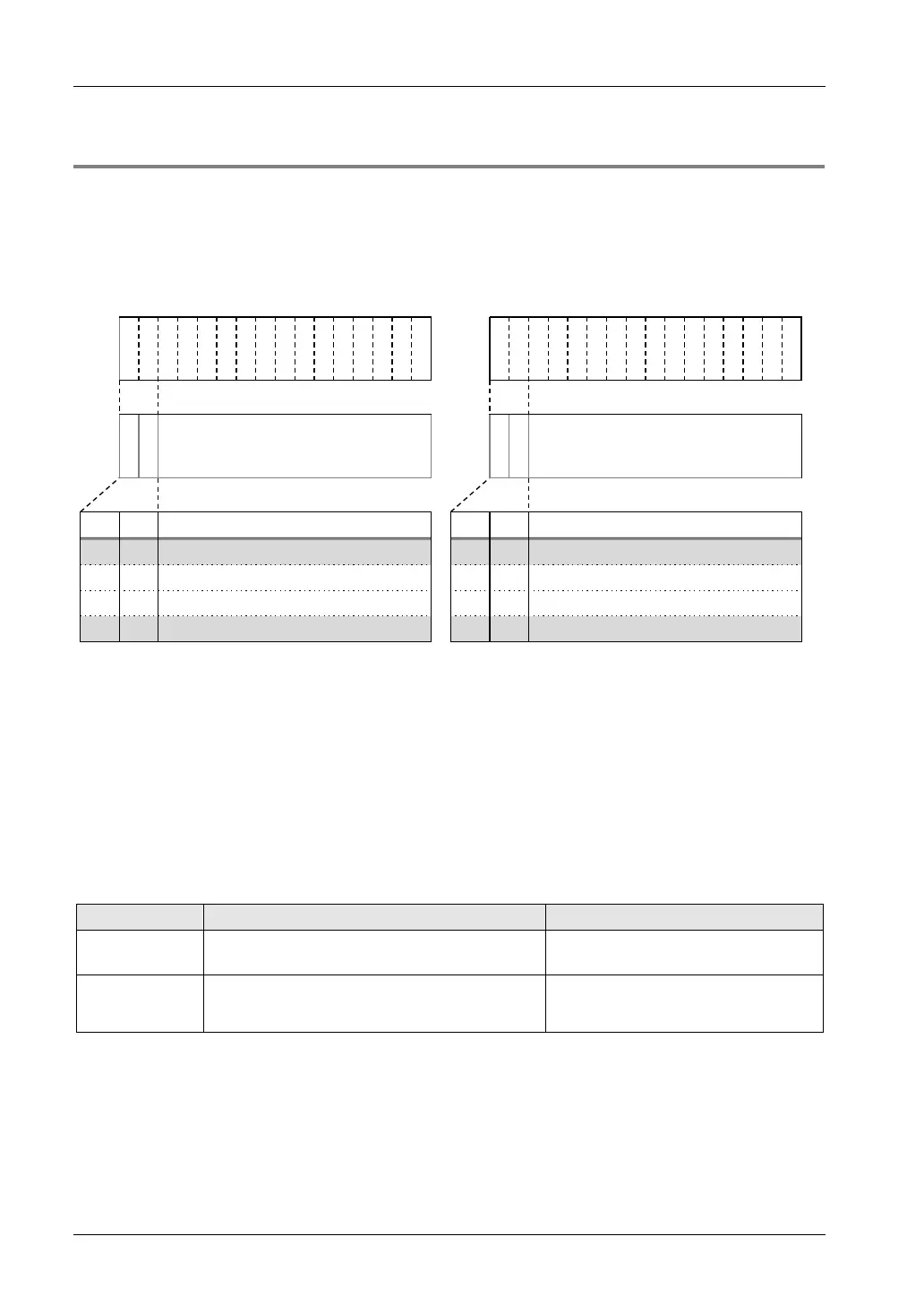
In the 14-bit mode, the most significant two bits are used as the switching flags. They are
common to the flags for setting ranges.
Y
3
F
Y
3
E
Y
3
D
Y
3
C
Y
3
B
Y
3
A
Y
3
9
Y
3
8
Y
3
7
Y
3
6
Y
3
5
Y
3
4
Y
3
3
Y
3
2
Y
3
1
Y
3
0
Y
2
F
Y
2
E
Y
2
D
Y
2
C
Y
2
B
Y
2
A
Y
2
9
Y
2
8
Y
2
7
Y
2
6
Y
2
5
Y
2
4
Y
2
3
Y
2
2
Y
2
1
Y
2
0
A
1
A
0
Output data of CH1/CH3 (14bit)
Range setting
A
1
A
0
Output data of CH0/CH2 (14bit)
Range setting
A1 A0
Item
A1
A0 Item
0 0 CH1 output range setting 0 0 CH0 output range setting
0 1
CH1 output data
0
1 CH0 output data
1 0 CH3 output data 1 0 CH2 output data
1 1 CH3 output range setting 1 1 CH2 output range setting
Writing data for conversion
• The analog output unit writes the analog output digital data of a maximum of 4 channels to
two memory areas (WY2/WY3) by user programs. Output data switching flags for specifying
channels are allocated to the two bits of the memory area (WY2/WY3).
• In user programs, channels are specified by setting/resetting the output channel swtiching
flag right after setting a digital value in the memory area.
• As CH0 and CH2, and CH1 and CH3 use each common memory area, data cannot be
written to the unit in the same scan. Write data separated into two scans using scan pulse
relay R9012, etc. In the channels which are not allocated to the same memory area, data
can be written in the same scan.
Example Processing Description
When CH0 and
CH1 are used
Writing CH0 data in WY2 at the time of “n” scan
Writing CH1 data in WY3 at the time of “n” scan
Data can be written in WY2 and WY3 at
the time of “n” scan.
When CH0 and
CH2 are used
Writing CH0 data in WY2 at the time of “n” scan
Writing CH2 data in WY2 at the time of “n+1” scan
Data can be written in WY2 once in 2
scanning processes (at the time of “n”
and “n+1” scan).

 Loading...


