4.4 Analog I/O Unit (FP0R-A21/A42)
4-29
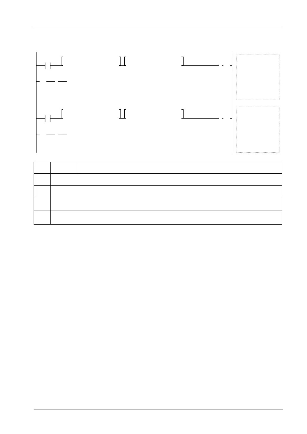
Sample program (12-bit mode: 0 to 20mA range)
<= K 0 , DT0
R9010
[ F0 MV , DT0 , WY2 ]
1
>
1
>
>= K 4000 , DT0
①
④
⑤
② ③
ⓐ
CH0
<= K 0 , DT1
R9010
[ F0 MV , DT1
, WY3
]
1
>
1
>
>= K 4000 , DT1
①
④ ⑤
② ③
ⓑ
CH1
①
R9010 Always ON relay
②
Checks whether the lower limit value is within the data range that the unit can convert correctly.
③
Checks whether the upper limit value is within the data range that the unit can convert correctly.
ⓐ
It is executed when the execution condition is ON and written data is within the upper and lower limits.
Data for CH0 is set in DT0, and CH0 is specified by the output data switching flag.
ⓑ
It is executed when the execution condition is ON and written data is within the upper and lower limits.
Data for CH1 is set in DT1, and CH1 is specified by the output data switching flag.

 Loading...


