4.4 Analog I/O Unit (FP0R-A21/A42)
4-33
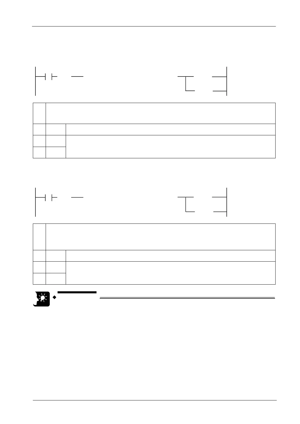
Sample program (Input range switching)
The following program shows the case that the input range of CH0 to CH3 of the first
expansion analog I/O unit (FP0R-A42/A21) is set.
[ F0 MV , HF0 , WY2 ]
R0
①
( )
DF
< SET >
< RST >
Y2E
Y2F
②
①
Input a constant for specifying an input range. Set it according to the I/O allocation on the previous page.
In the above sample program, HF0 is input for setting Y27-Y24 to 1 and Y23-Y20 to 0.
The range for CH3/CH2 is 0 to 5 V/0 to 20 mA, and that for CH1/CH0 is -10 V to +10 V.
②
WY2 Set it for switching the input range.
③
Y2E
Data switching flags. When Y2E is ON and Y2F is OFF, the input range is set.
④
Y2F
Sample program (Input averaging switching)
The following program shows the case that the averaging processing method of CH0 to CH3
of the first expansion analog I/O unit (FP0R-A42/A21) is set.
[ F0 MV , HF0 , WY3 ]
R0
①
( )
DF
< SET >
< RST >
Y3E
Y3F
②
①
Input a constant for specifying an averanging method. Set it according to the I/O allocation on the previous
page.
In the above sample program, HF0 is input for setting Y37-Y34 to 1 and Y33-Y30 to 0.
The method of CH3/CH2 is no averaging processing, and that of CH1/CH0 is moving average 10 times.
②
WY3 Set it for switching the averaging processing method.
③
Y3E
Data switching flags. When Y3E is ON and Y3F is OFF, the averaging method of input is set.
④
Y3F
• The input range setting and the input averaging method for four channels
are set collectively.

 Loading...


