4.4 Analog I/O Unit (FP0R-A21/A42)
4-35
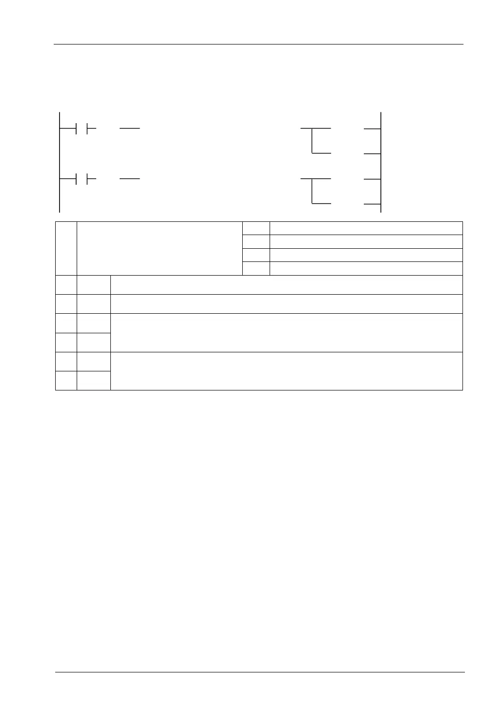
Sample program (Output range switching)
The following program shows the case that the input range of CH0 and CH1 of the first
expansion analog I/O unit (FP0R-A21/A42) is set.
[ F0 MV , H30 , WY2 ]
R0
①
( )
DF
< RST >
< SET >
Y2E
Y2F
②
[ F0 MV , H30 , WY3 ]
R0
①
( )
DF
< RST >
< SET >
Y3E
Y3F
③
①
Input a constant for specifying an output
range.
H30 -10 to +10V / 0 to 20mA
H31 -5 to +5V / 4 to 20mA
H32 0 to 10V
H33 0 to 5V
②
WY2 Set it for switching the output range of CH0.
③
WY3 Set it for switching the output range of CH1.
④
Y2E
Output data switching flag for CH0. When Y2E is OFF and Y2F is ON, the output range of CH0 is
set.
⑤
Y2F
⑤
Y3E
Output data switching flag for CH1. When Y3E is OFF and Y3F is ON, the output range of CH1 is
set.
⑦
Y3F

 Loading...


