When "Start code STX" is set to "Enabled", the maximum amount of sent data that can be specified is
decremented by one.
When "Terminator setting" is set to "ETX" or "CR", the maximum amount of sent data is decremented
by one.
When "Terminator setting" is set to "CR+LF", the maximum amount of sent data is decremented by
two.
When "Terminator setting" is set to "Time", the maximum amount of sent data is not decremented.
■
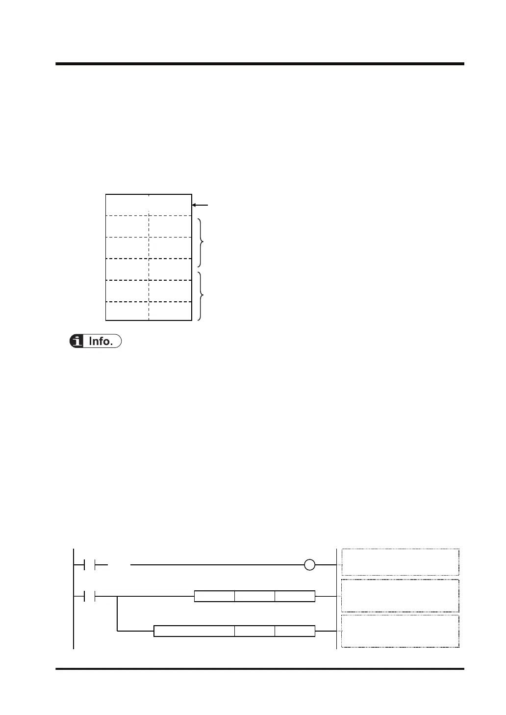
Storage method for received data
----- -----
Received data are stored in ascending order from lower bytes.
DT200
H32(2) H31(1)
H34(4) H33(3)
----- H35(5)
----- -----
DT201
DT202
DT203
DT204
Received number of bytes are stored.
U5
-----
If the number of received bytes is smaller than the area
specified by the GPRECV instruction, the value is not
overwritten.
● The case of SCU shows the case that it is used in the following combination.
• COM.0 port equipped in the CPU unit
• Communication cassettes attached to the CPU unit (COM.1 to COM.2 ports)
• Communication cassettes attached to the serial communication unit (COM.1 to COM.4
ports)
● As the communication cassette (Ethernet type) has an Ethernet-serial conversion function, the
internal interface operates with similar programs as the case of SCU. The setting method and
programming method are different from those for the CPU with built-in ET-LAN.
■
Sample program (in the case of SCU)
● When the received flag (X0) turns ON, the reception program is started up by the GPRECV
instruction.
● Using the UNITSEL instruction, specify the slot number (U0) and the COM. port number
(U1).
● In the GPRECV instruction, specify and execute the start of the data table that stores the
received message (DT200) and the final address (DT209).
GPRECV .US
DT209DT200
R100
UNITSEL U1U0
GPRECV processing
D1: Header for received data (DT200)
D2: End for received data (DT209)
GPRECV execution condition
Received flag: ON
S1 S2
Communication port settings
S1: Slot 0 built-in CPU (U0)
S2: COM1 (U1)
9.4 Receiving Operation
WUME-FP7COM-07 9-23

 Loading...


