Installation and Wiring
FPΣ User's Manual
86
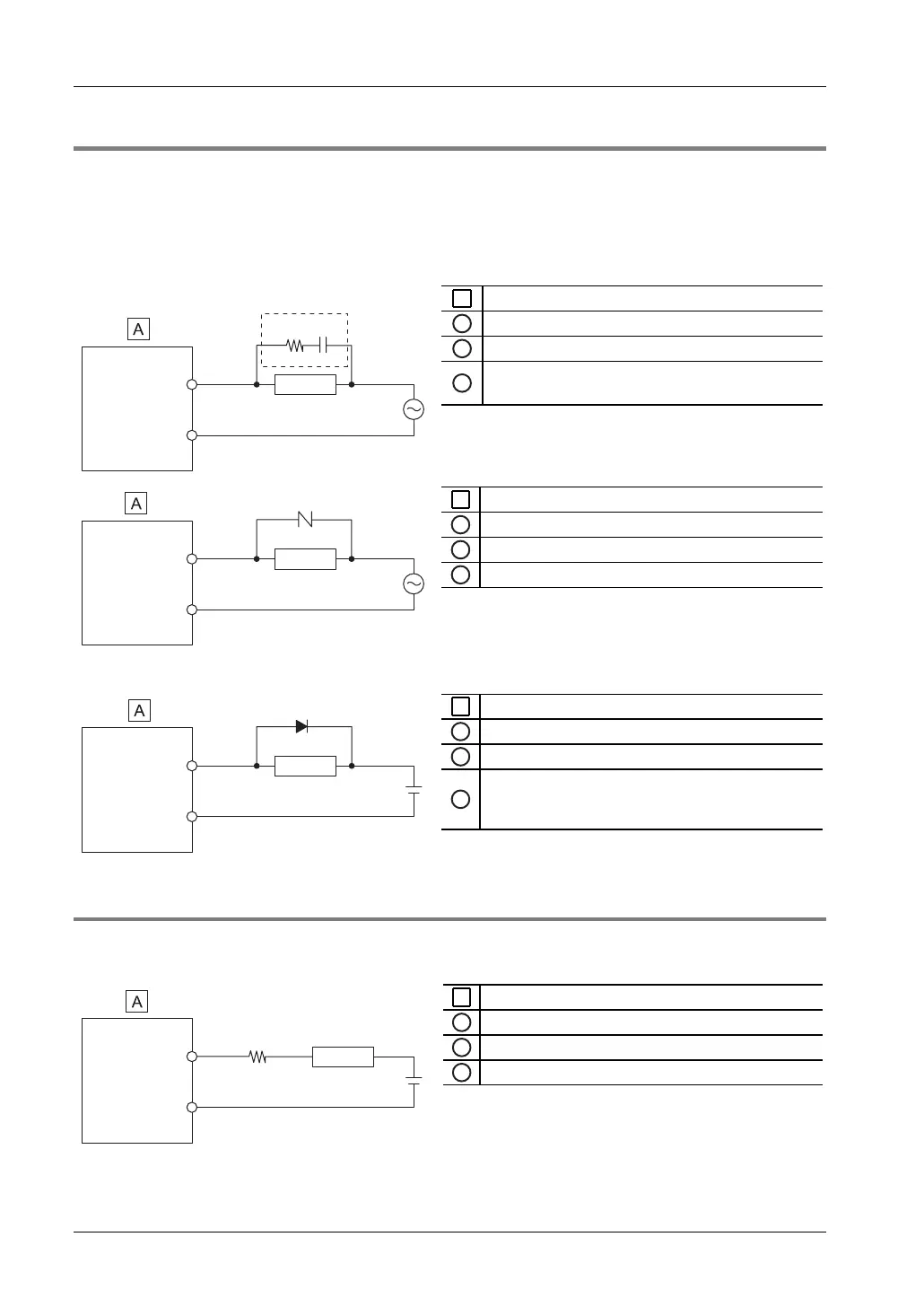
6.4.2.1 Protective Circuit for Inductive Loads
With an inductive load, a protective circuit should be installed in parallel with the load.
When switching DC inductive loads with the relay output type, be sure to connect a diode
across the ends of the load.
Using an AC inductive load (relay output type)
A
FPΣ
1
Output terminal
2
Load
3
Surge absorber, e.g. resistance R: 50Ω,
capacitance C: 0.47μF
COM
2
1
3
R
C
A
FPΣ
1
Output terminal
2
Load
3
Varistor
COM
2
1
3
Using a DC inductive load
A
FPΣ
1
Output terminal
2
Load
3
Diode; reverse voltage (V
R
): 3 × load voltage,
average rectified forward current (I
0
): ≥ load current
or more
COM
2
1
3
6.4.2.2 Protective Circuit for Capacitive Loads
When connecting loads with large in-rush currents, connect a protection circuit as shown
below to minimize their effect.
A
FPΣ
1
Output terminal
2
Load
3
Resistor
COM
2
1
3