FPΣ User's Manual
7.3 High-Speed Counter Function
113
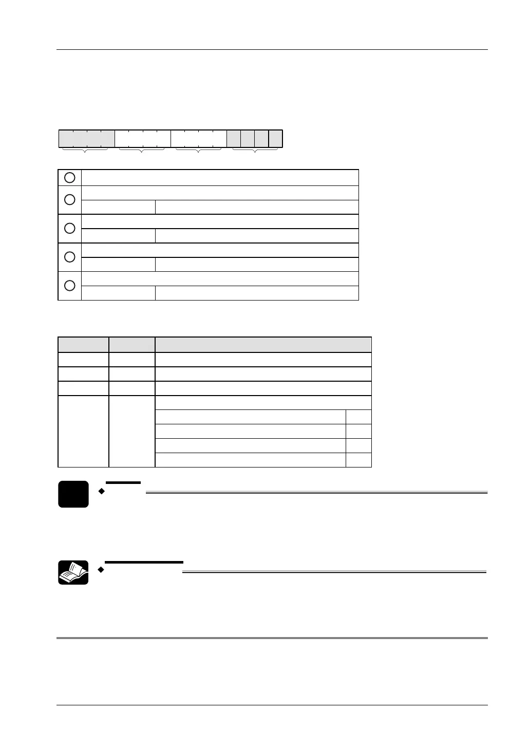
Control code settings
Bits 0–15 of the control code are allocated in groups of four. The bit setting in each group is
represented by a hex number (e.g. 0002 0000 0000 1001 = 16#2009).
15 12 11 8 7 4 3 0
IIIIIIIV
1
Channel number (channel n: 16#n)
Clear high-speed counter instruction (bit 3)
2
0: continue 1: clear
Reset input (bit 2) (see note)
3
0: enabled 1: disabled
Count (bit 1)
4
0: permit 1: prohibit
Reset elapsed value to 0 (bit 0)
5
0: no 1: yes
Example: 16#2009
Group Value Description
IV 2 Channel number: 2
III 0 (fixed)
II 0 (fixed)
Hex 9 corresponds to binary 1001
Clear high-speed counter instruction: clear (bit 3) 1
Reset input: enabled (bit 2) 0
Count: permit (bit 1) 0
I 9
Reset elapsed value to 0: yes (bit 0) 1
NOTE
Use the reset input setting (bit 2) to disable the reset input allocated in the
system registers.
REFERENCE
Please refer to the FPWIN Pro online help for programming examples.
7.3.4.2 Writing and Reading the Elapsed Value for the High-Speed Counter
The elapsed value is stored as a double word in the special data registers. Access the special
data registers using the system variable sys_diHscChannelxElapsedValue (where x=channel
number).