FPΣ User's Manual
7.5 PWM Output Function
151
7.5 PWM Output Function
Use the instruction F173_PulseOutput_PWM. This instruction delivers a pulse width
modulated output signal according to the specified DUT.
The PWM output status is stored in special internal relays. To access special data registers
and special internal relays, use the PLC-independent system variables. You can insert system
variables directly into the POU body: Use the "Variables" dialog without entering a declaration
in the POU header. Please refer to the FPWIN Pro online help for detailed information on
using system variables.
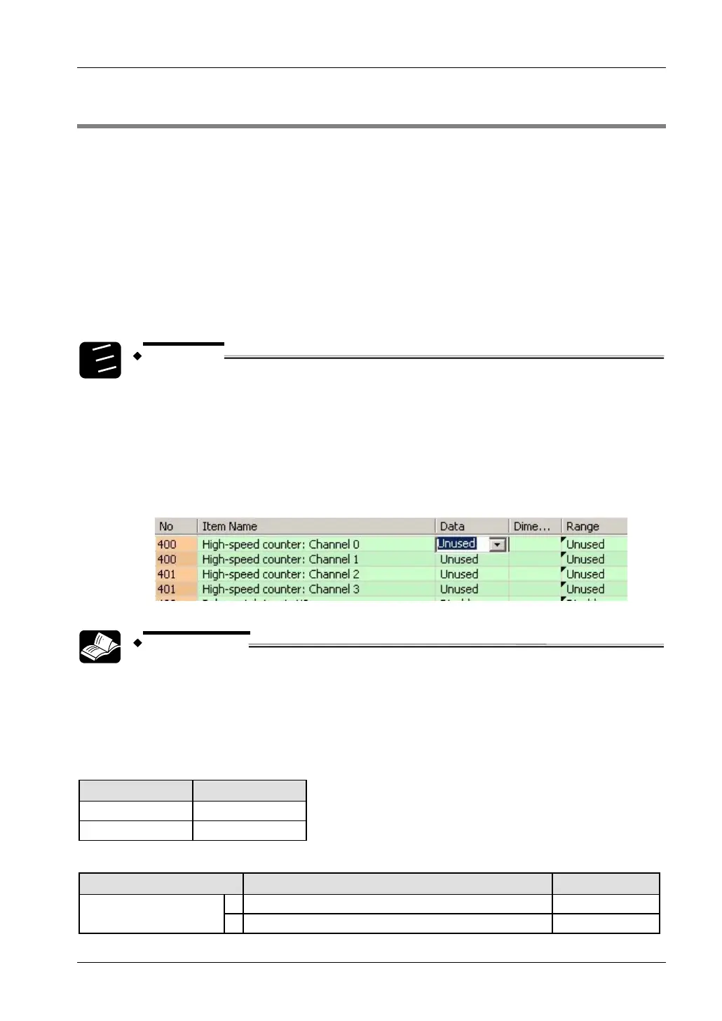
Setting system registers
When using the PWM output function, make sure the high-speed counter function is not
allocated to channel 0 or channel 2.
1.
2.
3.
Procedure
1. Double-click "PLC" in the navigator
2. Double-click "System Registers"
3. Double-click "High-Speed Counter, Pulse-Catch Input, Interrupt Input"
4. Set the high-speed counters allocated to channel 0 and channel 2 to
"Unused"
REFERENCE
Please refer to the FPWIN Pro online help for details and a programming
example.
Output relays and system variables for FPΣ
Channel and pulse output numbers
Channel no. Pulse output
0 Y0
2 Y3
System variables for memory areas used
Description System variable Address
0 sys_bIsPulseChannel0Active R903A
Pulse output: control flag
for channel
2 sys_bIsPulseChannel2Active R903C