FPΣ User's Manual
7.4 Pulse Output Function
149
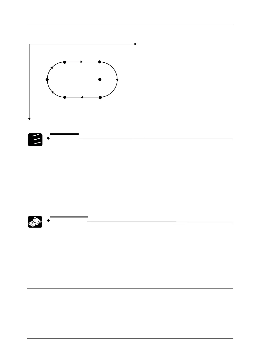
Positioning path
P1 (0, 0) P2 (10000, 0)
P4 (0, 10000) P3 (10000, 10000)
Q
(10000, 5000)
S (-5000, 5000)
Y
X
1.
2.
3.
Procedure
1. As the action that follows circular interpolation control is linear
interpolation, select stop mode in the control code.
2. The rotation direction during circular interpolation is the same direction for
both P2 to P3 and P4 to P1. Designate rotation direction 1 in the control
code.
3. Use the circular interpolation control flag
(sys_bIsCircularInterpolationActive) to confirm completion of the circular
interpolation action.
REFERENCE
For POU Header and POU Body, please see the programming examples in
Panasonic's download area.
Applicable FPWIN Pro Project:
• Sample_PulseOutput_06_Linear_and_Circular_Interpolation_LD_FP_SIGMA.pro
• Sample_PulseOutput_06_Linear_and_Circular_Interpolation_ST_FP_SIGMA.pro
7.4.4.7 Example 7: Circular Interpolation, Continue Mode
This is an example program that continually executes the circular interpolation action.
Positioning starts at P1 (0,0). The target value is overwritten three times before the final
position P4 is reached. The wiring diagram shown above applies to this program. See page
138.
Let channel 0 be the X-axis and channel 2 be the Y-axis.