FPΣ User's Manual
12.2 Performance Specifications
279
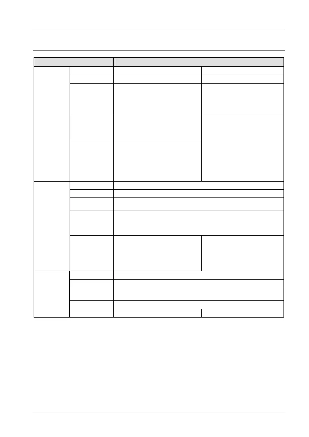
12.2.1 High-Speed Counter, Pulse Output and PWM Output Specifications
Item Descriptions
No. of channels
Single-phase: ≤4 Two-phase: ≤2
Channels used
1)
0–4 0, 2
Maximum
counting speed
Single-phase:
for 1 channel: ≤50kHz (x 1)
for 2 channels: ≤0kHz (x 2)
for 3 or 4 channels:
≤20kHz (x 3 or x 4)
Two-phase:
for 1 channel: ≤20kHz (x 1)
for 2 channels:
≤15kHz (x 2)
Input mode
Single-phase:
Incremental
Decremental
Two-phase:
Two-phase
Incremental/decremental
Incremental/decremental control
High-speed
counter
Input used
2)
Single-phase:
X0: Counter input (channel 0)
X1: Counter input (channel 1)
X2: Reset input (channel 0, 1)
X3: Counter input (channel 2)
X4: Counter input (channel 3)
X5: Reset input (channel2, 3)
Two-phase:
X0, X1: Counter input (channel 0)
X2:Reset input (channel 0)
X3, X4: Counter input (channel 2)
X5: Reset input (channel 2)
No. of channels
Max. 2
Channels used
1)
0, 2
Pulse output
method
CW/CCW, Pulse/direction
Maximum output
frequency
1 channel: ≤100kHz (x 1)
2 channels: ≤60kHz (x 2)
(Linear interpolation control:
≤100kHz
Circular interpolation control:
≤20kHz)
Pulse output
Input/output
used
2)
Channel 0:
X2: Home input
Y0:CW pulse output/Pulse output
Y1: CCW pulse output/Direction output
Y2: Deviation counter clear output
Channel 2:
X5: Home input
Y3:CW pulse output/Pulse output
Y4: CCW pulse output/Direction
output
Y5: Deviation counter clear output
No. of channels
Max. 2
Channels used
1)
0, 2
Output
frequency
1.5–12.5kHz (at resolution of 1000), 15.6k–41.7kHz (at resolution of 100)
Duty ratio
0.0–99.9% (at resolution of 1000), 1–99% (at resolution of 100)
PWM output
Output used
2)
Channel 0: Y0 Channel 2: Y3
1)
The same channel cannot be used by more than one function.
2)
The inputs and outputs cannot be allocated to more than one function.
Inputs and outputs that have been allocated to a high-speed counter or pulse output function cannot be used
as normal inputs or outputs.
X0–X5 can also be used as pulse catch inputs or interrupt inputs.