FPΣ User's Manual
8.7 PLC Link
235
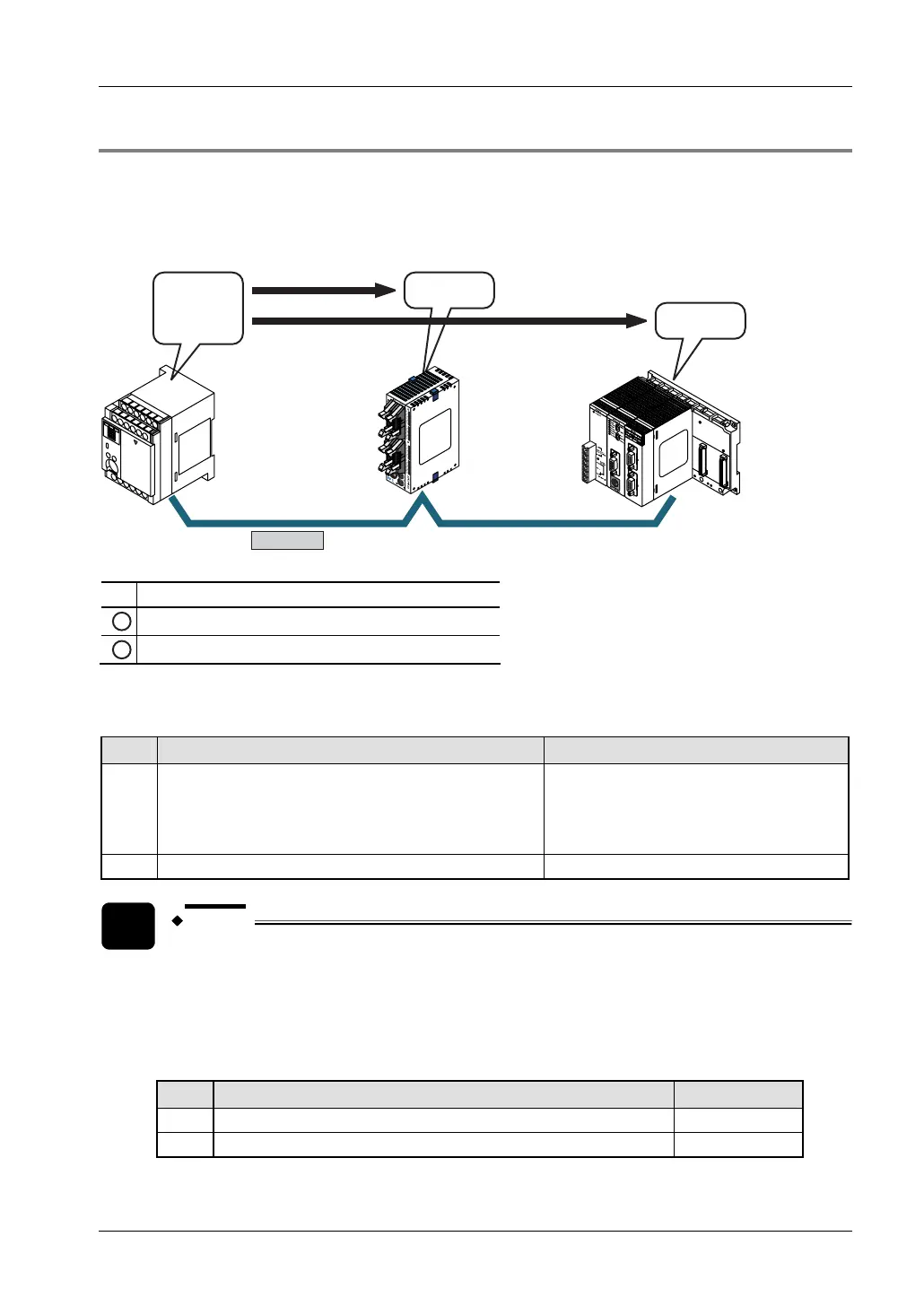
8.7.6 Connection Example
The following example demonstrates how the PLC can be connected to two other PLCs using
a PLC link connection. In the example shown here, link relays are used. When X1 of station
number 1 turns to TRUE, Y1 of station number 2 turns to TRUE. When X2 of station number 1
turns to TRUE, Y1 of station number 3 turns to TRUE.
RS485
FP2/FP2SHFP-X FPΣ
X1: TRUE
X2: TRUE
Y0: TRUE
Y0: TRUE
#1 #2 #3
# Station number of PLC
1
Link relay L0 turns to TRUE
2
Link relay L1 turns to TRUE
System register settings
For PLC Link, the communication format and baud rate settings are fixed:
No. Name Set value
413 COM port 1 - communication format
Data length: 8 bits
Parity: Odd
Stop bit: 1 bit
End code: CR
Start code: No STX
415
COM port 1 - baud rate 115200bit/s
NOTE
FPG-COM4: The baud rate of 115200bit/s must be set with switch SW1-2 on the
cassette. See "
DIP Switch Setting on FPG-COM4" on page 162.
Set communication mode and station numbers using the system registers:
• Settings for FP-X (station number 1)
No. Name Set value
410
COM port 1 - station number 1
412
COM port 1 - communication mode PLC Link