High-Speed Counter and Pulse Output
FPΣ User's Manual
102
7.2 Function Specifications and Restrictions
This section contains the specifications and restrictions of the high-speed counter, pulse
output, and PWM output function.
7.2.1 High-Speed Counter Function
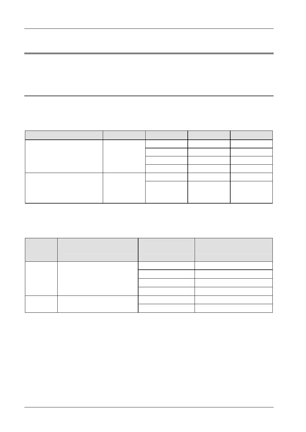
For each count input mode, there are certain high-speed counter channels, inputs, and
memory areas.
Input numbers
Input mode
1)
No. of phases Channel no. Input Reset input
2)
0 X0 X2
1 X1 X2
2 X3 X5
• Incremental
• Decremental
1
3 X4 X5
0 X0, X1 X2
• Two-phase
• Incremental/decremental
• Incremental/decremental
control
2
2 X3, X4 X5
1)
For details on the different input modes,.
2)
Reset input X2 can be set to either channel 0 or channel 1. Reset input X5 can be set to either channel 2 or
channel 3.
Performance
No. of
phases
Minimum input pulse width
1)
No. of channels Maximum counting speed
1 50kHz
2
30kHz (×2 channels)
3
20kHz (×3 channels)
1
10μs (100μs)
2)
4
20kHz (×4 channels)
1 20kHz
2
25μs (100μs)
2)
2
15kHz (×2 channels)
1)
For information on the minimum input pulse width, see page 109.
2)
The values in parentheses refer to the reset input.
Control flags and memory areas
The high-speed counter operating status, counting values, and control code are stored in
special internal relays and special data registers. The control code contains the counter
settings. To access special data registers and special internal relays, use the PLC-
independent system variables. You can insert system variables directly into the POU body:
Use the "Variables" dialog without entering a declaration in the POU header. See "
Instructions
and system variables" on page
110.