Installation and Wiring
FPΣ User's Manual
80
6.3.1 Grounding
If necessary, ground the instrument to increase the noise resistance.
NOTE
• For grounding purposes, use wiring with a minimum of 2mm
2
. The
grounding connection should have a resistance of less than 100Ω.
• The point of grounding should be as close to the PLC as possible. The
ground wire should be as short as possible.
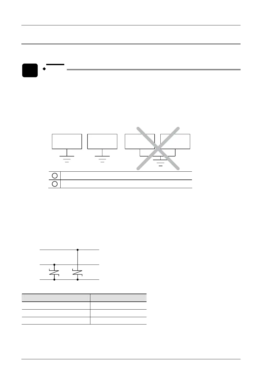
• If two devices share a single ground point, it may produce an adverse
effect. Always use an exclusive ground for each device.
OK
1
PLC
2
Other device (inverter etc.)
Risk of short circuits
Depending on the surroundings in which the equipment is used, grounding may cause
problems.
Example1:
Since the power supply lines of the FPΣ and of the FP0 expansion unit (24V DC and 0V
terminal) are connected to the function earth (PE) through a varistor, the varistor may be
shorted if there is an irregular potential between the power supply line and function earth.
24V DC
PE
0V
Power supply line of FP
Σ
or FP0 expansion unit
Unit type Varistor
FPΣ C32, C28
82V
FPΣ C24
56V
FP0 expansion unit 39V