FPΣ User's Manual
8.2 Communication Cassettes
161
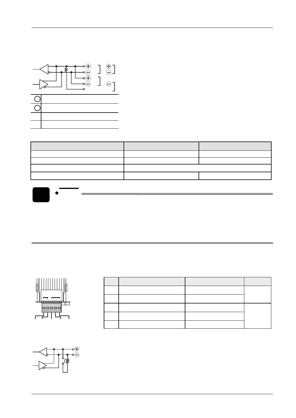
Bridge the E terminal and the free (-) terminal on the first and on the last station of the
transmission line to terminate the data bus.
b
E
a
1
2
E
1
General station
2
First and last station
a Open
b Bridge
Communication modes
Communication mode 1:1 communication 1:N communication
MEWTOCOL-COM Master/Slave — X
Program controlled — X
PLC Link X
Modbus RTU Master/Slave — X
NOTE
This communication cassette always sends two stop bits and accepts 1 as well
as 2 stop bits during reception, regardless of the stop bit setting.
8.2.5 FPG-COM4: 1-Channel RS485 and 1-Channel RS232C Combination Type
This communication cassette contains a 1-channel unit with a two-wire RS485 port and a 1-
channel unit with a three-wire RS232C port.
Terminal layout
+
-
SD RD SG
FPG-COM4
AFPG806
RS232CRS485
SD RD SG
-
+
Pin Name Signal direction Port
+
Transmission line (+)
—
-
Transmission line (-)
—
RS485
(COM 1)
SD
Send Data
PLC → External device
RD
Receive Data
PLC ← External device
SG
Signal Ground
—
RS232
(COM 2)
Set SW1-1 to ON on the first and on the last station of the transmission line to terminate the
data bus. See also "
DIP Switch Setting on FPG-COM4" on page 162.
SW1-1