High-Speed Counter and Pulse Output
FPΣ User's Manual
150
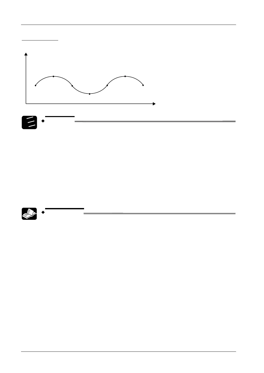
Positioning path
P
1
S
1
P
2
S
2
S
3
P
3
P
4
(0, 0)
(500, 250)
(1000, 0)
(1500, -250)
(2000, 0)
(2500, 250)
(3000, 0)
X
Y
1.
2.
3.
Procedure
1. To overwrite the data after startup use the target value overwrite flag
(sys_bIsCircularInterpolationOverwritingPossible) and a shift register.
2. In control that heads towards final point P4, switch the control code to stop
mode.
3. In this example, since the rotation direction changes for each positioning
point, designation of the rotation direction is as follows:
1) Between P1 and P2: rotation direction 0
2) Between P2 and P3: rotation direction 1
3) Between P3 and P4: rotation direction 0
REFERENCE
For POU Header and POU Body, please see the programming examples in
Panasonic's download area.
Applicable FPWIN Pro Project:
• Sample_PulseOutput_07_Circular_Interpolation_LD_FP_SIGMA.pro
• Sample_PulseOutput_07_Circular_Interpolation_ST_FP_SIGMA.pro