Communication
FPΣ User's Manual
226
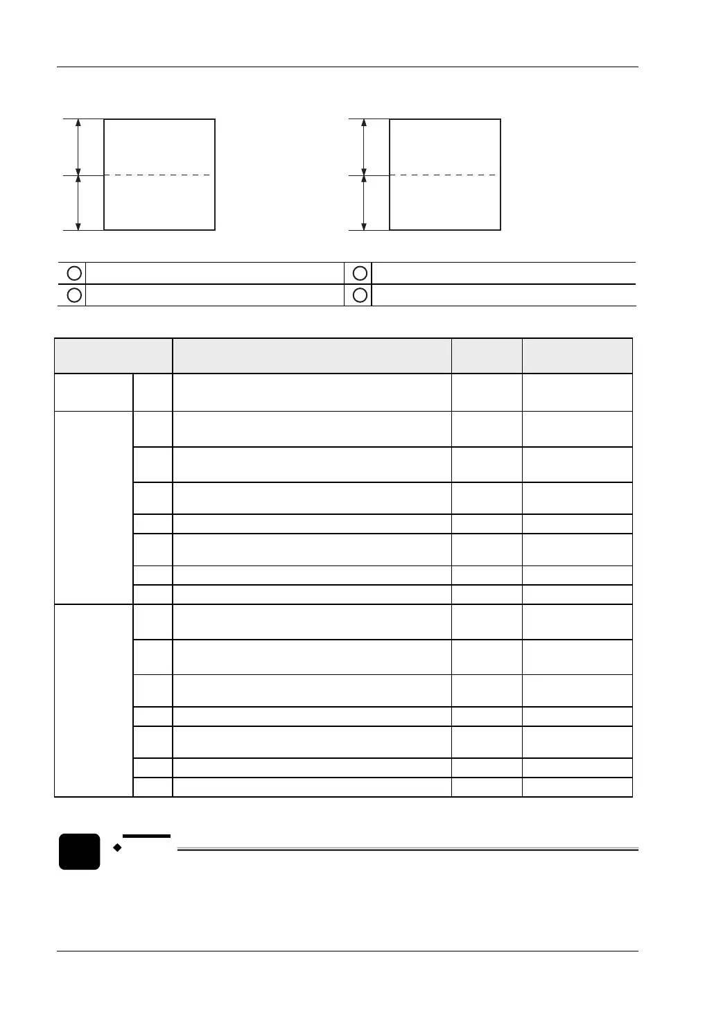
Link relays Link registers
0
63
64
127
0
127
128
255
Unit: words
1
For PLC link 0: 1024 points (1st half)
1
For PLC link 0: 128 words (1st half)
2
For PLC link 1: 1024 points (2nd half)
2
For PLC link 1: 128 words (2nd half)
System registers
No. Name
Default
value
Set values
46 PLC Link 0 and 1 allocation setting Normal Normal: 1st half
Reverse: 2nd half
40 Link relays - Send/receive area - Number of words
shared by all linked PLCs
0 0-64 words
41 Link registers - Send/receive area - Number of words
shared by all linked PLCs
0 0-128 words
42 Link relays - Send area - Start sending from this word
address
0 0-63
43 Link relays - Send area - Number of words to send 0 0-64 words
44 Link registers - Send area - Start sending from this
word address
0 0-127
45 Link registers - Send area - Number of words to send 0 0-128 words
PLC link 0
47
1)
Highest station number in network 16 1-16
50 Link relays - Send/receive area - Number of words
shared by all linked PLCs
0 0-64 words
51 Link registers - Send/receive area - Number of words
shared by all linked PLCs
0 0-128 words
52 Link relays - Send area - Start sending from this word
address
64 64-127
53 Link relays - Send area - Number of words to send 0 0-64 words
54 Link registers - Send area - Start sending from this
word address
128 128-255
55 Link registers - Send area - Number of words to send 0 0-128 words
PLC link 1
57
1)
Highest station number in network 0 0-16
1)
Set the same value for all PLCs in the link.
NOTE
Use the SYS2 instruction to set the link area in RUN mode. Please refer to the
FPWIN Pro online help for detailed information.