FPΣ User's Manual
12.5 Relays and Memory Areas
291
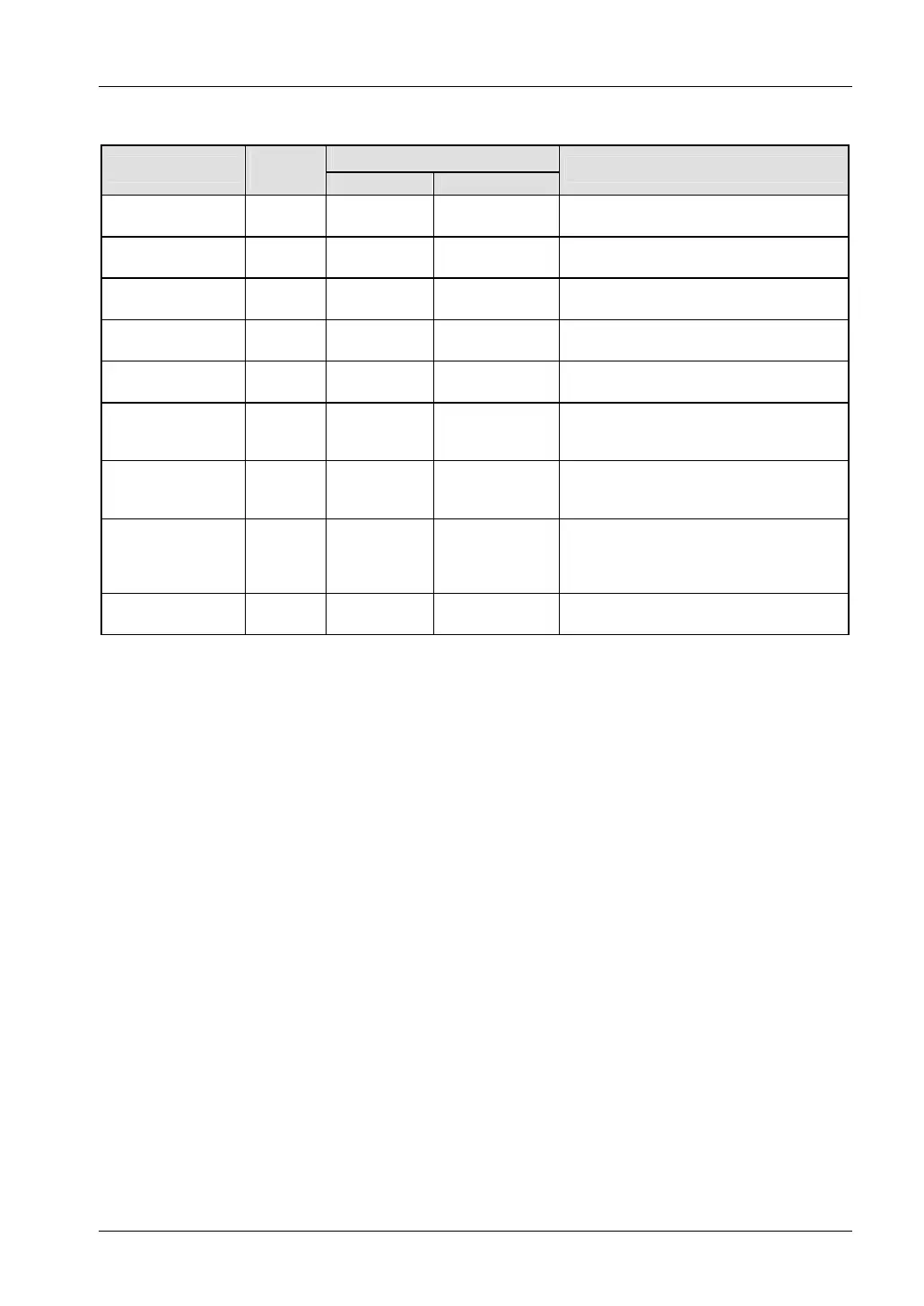
Memory area [double words]
Available address area
Type
Memory
size
FP IEC
Function
External input
relays
1)
37
DWX0–
DWX72
%ID0–
%ID72
Code for specifying 32 external input
points as a double word (32 bits) of data.
External output
relays
1)
37
DWY0–
DWY72
%QD0–
%QD72
Code for specifying 32 external output
points as a double word (32 bits) of data.
Internal relays
2)
128
DWR0–
DWR254
%MD0.0–
%MD0.254
Code for specifying 32 internal relay points
as a double word (32 bits) of data.
Link relays 64
DWL0–
DWL126
%MD7.0–
%MD7.126
Code for specifying 32 link relay points as
a double word (32 bits) of data.
Data registers
2)
16382
DDT0–
DDT32763
%MD5.0–
%MD5.32763
Data memory used in a program. Data is
handled in 32-bit units (double word).
Link registers
2)
128
DLD0–
DLD254
%MD8.0–
%MD8.254
Data memory shared by multiple PLCs
connected using PLC link. Data is handled
in 32-bit units (double word).
Timer/counter set
value area
2)
512
DSV0–
DSV1022
%MD3.0–
%MD3.1022
Data memory for storing the set values of
timers or counters. The values are stored
by timer/counter number.
Timer/counter
elapsed value area
2)
512
DEV0–
DEV1022
%MD4.0–
%MD4.1022
Data memory for storing the elapsed
values during operation of timers or
counters. The values are stored by
timer/counter number.
Special data
registers
130
DDT90000–
DDT90258
%MD5.90000–
%MD5.90258
Data memory for storing settings and error
codes.
1)
The number of points noted above is the number reserved as the calculation memory. The actual number of
points available for use is determined by the hardware configuration.
2)
If no battery is used, only the fixed area is backed up.
Counter relays: 16 (C1008–C1023)
Internal relays: 128 (R900–R97F)
Data registers: DT32710–DT32764.
If the optional battery is used, the data in the hold and non-hold areas specified in the system registers will
be backed up.
If the battery is empty or no battery is present and additional hold areas have been defined, the hold/non-
hold operation becomes unstable. The data value will become indefinite. It is not cleared to 0 the next time
the power is turned on. Do not forget to monitor the battery status or to reset the hold areas to the default
values if no battery is used. See "
Backup Battery" on page 95.
3)
The number of points for timer and counter relays can be changed using system register 5. The numbers in
the table are the default settings.