FPΣ User's Manual
3.1 Parts and Functions
17
LED Description
Lights when in RUN mode and indicates that the program is being executed.
RUN (green)
Flashes during forced input/output (RUN and PROG. LEDs flash alternately).
Lights when in PROG mode and indicates that operation has stopped.
PROG. (green)
Flashes during forced input/output (RUN and PROG. LEDs flash alternately).
Flashes when an error is detected by the self-diagnostic function (ERROR).
ERROR/ALARM (red)
Lights if a hardware error occurs, or if operation slows because of the program,
and the watchdog timer is activated (ALARM).
2
Operation mode selector
Used to change the operation mode of the PLC.
Switch position Operation mode
RUN (upward)
Sets RUN mode. The program is executed and operation begins.
PROG. (downward)
Sets PROG mode. Operation stops. Programming via the TOOL port is possible.
When performing remote switching with the programming tool, the position of the operation
mode selector and the actual operation mode may differ. Verify the mode with the operation
status LED. Otherwise, restart the FPΣ and set the operation mode using the operation mode
selector.
3
Communication status LEDs
Display the communication status of COM port 1 and COM port 2.
LED Description
Flashes while data is being transmitted
S Send data monitor
Goes out when no data is being transmitted
Flashes while data is being received
COM.1
R
Receive data
monitor
Goes out when no data is being received
Flashes while data is being transmitted (always ON for 1-channel
RS232C type when the RS signal is ON)
S Send data monitor
Goes out when no data is being transmitted
Flashes while data is being received (always ON for 1-channel RS232C
type when the CS signal is ON)
COM.2
R
Receive data
monitor
Goes out when no data is being received
4
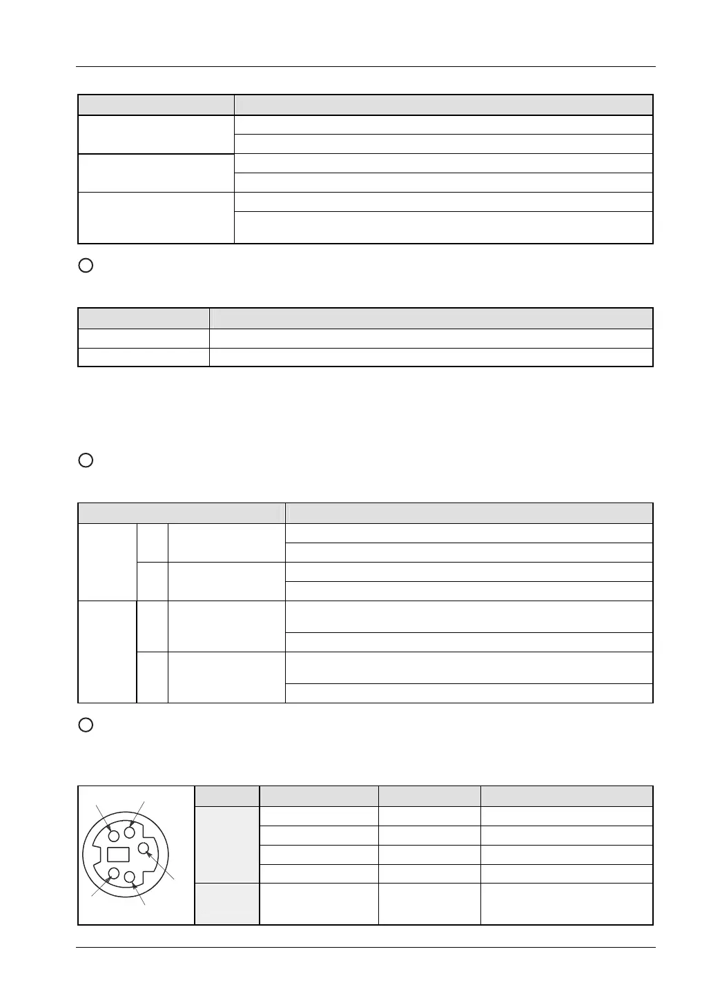
TOOL port (RS232C)
Used to connect a programming tool.
A commercial 5-pin mini DIN connector is used for the TOOL port on the CPU.
Pin no. Signal name Abbreviation Signal direction
1
Signal Ground SG –
2
Send Data SD CPU → External device
3
Receive Data RD CPU ← External device
4
(Not used) – –
1
3
5
4
2
5 +5V +5V CPU → External device