Version 7.11
18 | Resistor Values for EOL and Tamper
Digiplex EVO • Programming Guide
Resistor Values for EOL and Tamper
Use the following section to select different resistor values for EOL and tamper.
Selectable Inputs
1. Enter panel section [4003].
2. Enter the module’s serial number.
3. Enter module section [402] (refer to Worksheet 6 on page 18). Each of the 8 digits represent one of the 8 inputs.
Worksheet 6: Zone Input Options
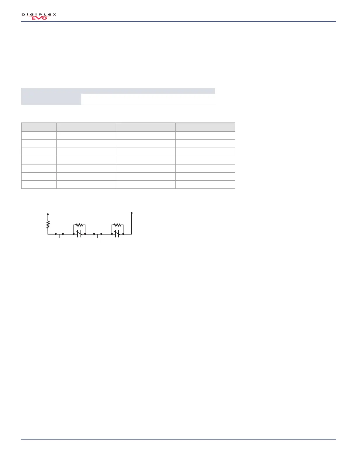
Figure 1: Selectable Input Resistor for EOL and Tamper
Keyswitch Programming
Use the following section to program keyswitches on your EVO192 control panel. Keyswitch programming information is entered in Worksheet 7 on page 20 and
Worksheet 8 on page 20.
Keyswitch Numbering
This feature allows the installer to assign a keyswitch to an addressable or hardwired detection device. To assign keyswitch numbering, proceed as follows:
1. Enter a section number between [0501] and [0532]. These sections represent keyswitches 1 to 32, respectively.
2. In column A, of Worksheet 7 on page 20, enter the eight-digit serial number of the module, to which the keyswitch is connected.
3. In column B, of Worksheet 7 on page 20, enter the three-digit input number of the module, to which the keyswitch is connected.
Keyswitch Parameters
This feature defines the keyswitch’s partition assignment and arming method. To assign keyswitch parameters, proceed as follows:
1. Enter a section number between [0601] and [0632]. These sections represent keyswitches 1 to 32, respectively.
2. In column C, of Worksheet 7 on page 20, enter the keyswitch definition (refer to Table 12 on page 19 for details). The default setting is set to disabled.
3. In column D, of Worksheet 7 on page 20, enter the desired partition to which the keyswitch is assigned (refer to Table 13 on page 19 for details). By default,
keyswitches are not assigned to a partition.
4. In column E, of Worksheet 7 on page 20, enter the keyswitch option (refer to Table 14 on page 19 for details). By default, all settings are set to OFF.
Section Input 1 / Input 2 Input 3 / Input 4 Input 5 / Input 6 Input 7 / Input 8
[0402]
Zone Input Options
_/_
(0/0)
_/_
(0/0)
_/_
(0/0)
_/_
(0/0)
Table 11: Zone Input Option Individual Settings
Option EOL Value Zone A Value Zone B Value (ATZ)
0 1K 1K 2K2
12K2 1K5 N/A
23K3 3K3 N/A
34K7 4K7 N/A
44K7 6K8 N/A
52K2 4K7 N/A
68K2 8K2 N/A
Zone
input
Zone A
TAMPER
EOL
value
TAMPERN.C. N.C.
Zone B (ATZ)
COM
 Loading...