13-7 The Default Applications
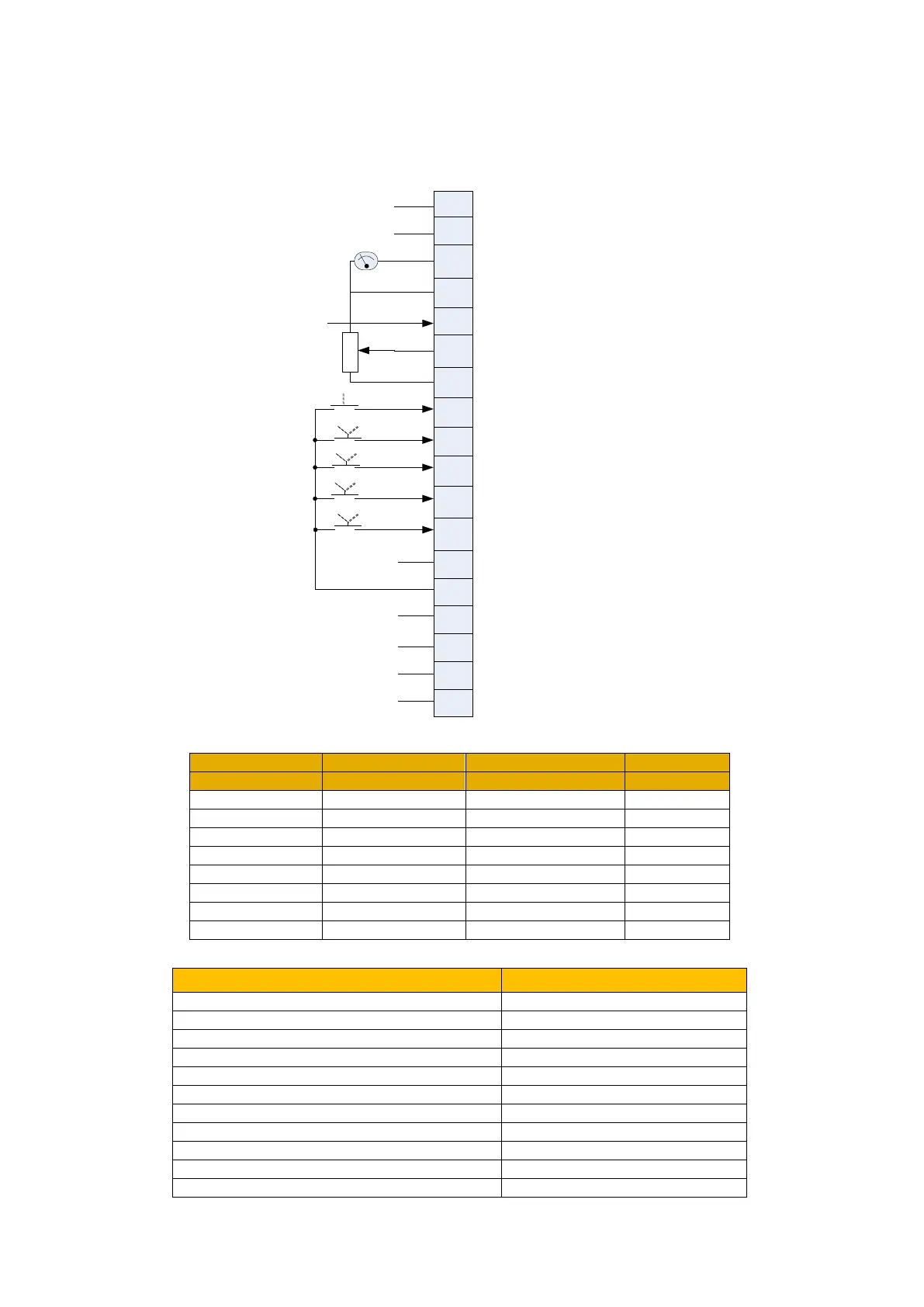
AC10 Inverter
This is ideal for applications requiring multiple discrete speed levels.
The set-point is selected from either the sum of the analogue inputs, or as one of up to eight
other pre-defined speed levels. These are selected using DI2, DI3 and DI4, refer to the Truth
Table below.
Preset Speed Truth Table
F203 Main frequency source X
4: Multi-stage speed control
F204 Accessorial frequency source Y
F207 Frequency source selecting
F316 DI1 terminal function setting
F317 DI2 terminal function setting
F318 DI3 terminal function setting
F319 DI4 terminal function setting
F320 DI5 terminal function setting
F431 AO1 analog output signal selecting
Coast stop
1
2
3
5
6
4
7
8
9
10
11
12
13
14
15
16
17
18
TA
TB
TC
1DO
24V
CM
DI1
DI2
DI3
DI4
DI5
10V
1AI
2AI
GND
1AO
A
B
REF
Run forward
Speed trim
not used
not used
Analog output
F431=0 , running
frequency is output.
GND
Speed trim AI2 input 4-20 mA
Speed setpoint AI 1 input 0-10V
10V
Coast stop
Preset select 1
Auto run
CM
24V
not used
Relay output
See truth table below
F300=1 , inverter outputs
fault signal.
See truth table below
Preset select 2
Preset select 3
See truth table below
Preset select 1
Preset select 2
Preset select
3

 Loading...


