7-3 Installation & Connection
AC10 Inverter
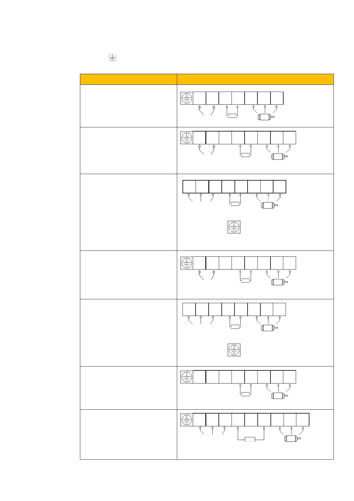
7.2 Connection
Connect R/L1, S/L2 and T/L3 terminals (L1/R and L2/S terminals for single-phase) with power
supply, to grounding, and U, V and W terminals to motor.
Motor shall have to be grounded. Otherwise connected motor causes interference.
1-phase 230V 0.2kW~0.75kW
Frame 2
1-phase 230V 1.1kW~2.2kW
3-phase 230V 0.2kW~0.75kW
3-phase 400V 0.2kW~0.55kW
Frame 2 – Frame 4
3-phase 400V 0.75kW~11kW
3-phase 230V 4kW~11kW
3-phase 400V 15kW~22kW
3-phase 230V 7.5kW~11kW

 Loading...


