The Keypad 5-1
AC10 Inverter
Chapter 5 The Keypad
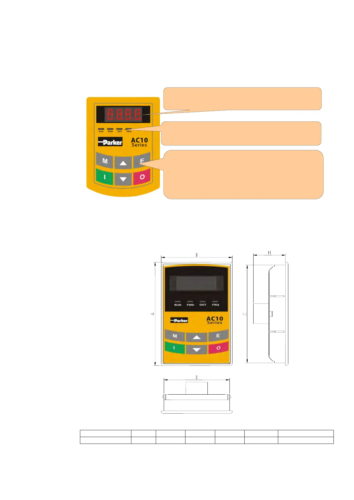
5.1 The Display
The panel covers three sections: data display section, status indicating section and
keypad operating section, as shown in Figure 5-1.
Figure 5-1 Keypad Display
5.2 Remote-control
The remote mounted keypad can be ordered as 1001-00-00.
This includes the keypad, cable and mounting brackets.
Layout diagram
Keypad Measurements (Unit:mm)
“DIGIT” (DGT) 4 LEDs indicate working status. RUN while running.
FWD running forward DGT showing digit selection and FRQ
when the MMI is showing frequency.
LED display shows running frequency, flashing target
frequency, function code, parameter value or fault code.
Press “M” for function code, and “E” for original
parameters.▲and▼keys can be used to select function
codes and parameters. Press “E” again to confirm. In the
mode of keypad control, ▲and▼keys can also be used
for dynamic speed control. “I” and “O” keys control start
and stop. Press “O” key to reset inverter in fault status.

 Loading...


