7-9 Installation & Connection
AC10 Inverter
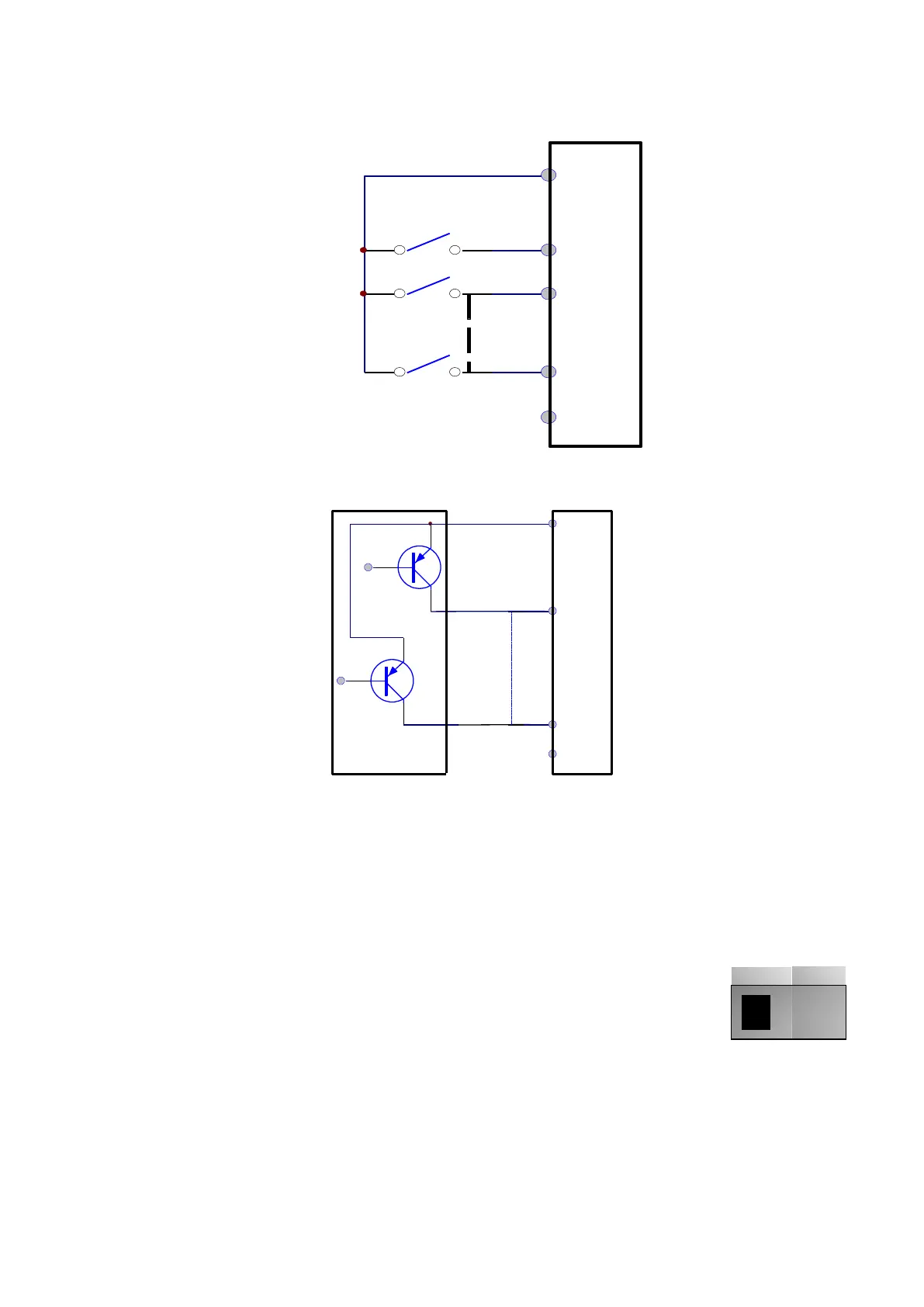
7.5.3 Wiring for positive Sink electrode (PNP mode) -- Switch J7 set for PNP.
7.5.4 Wiring for active drain electrode (PNP mode) (Common Collector Mode)
The most prevalent wiring mode for I/O depends on where the system is located. In many
parts of the world “sink or pull-down” configurations are used, and PNP mode is generally
used. In many other parts of the world “source or pull-up” configurations are used, and NPN
mode is typically used. The user should choose wiring mode according to the application
requirement.
Instructions of choosing NPN mode or PNP mode:
1. There is a toggle switch J7 near to control terminals.
See Figure 7-2.
2. When turning J7 to “NPN”, DI terminal is connected to CM for
TRUE.
3. When turning J7 to “PNP”, DI terminal is connected to 24V for
TRUE.
NOTE: J7 is on the back of control board for single-phase inverter 0.2-0.75KW.
K1
K2
K6
DI1
DI2
DI8
CM
24V
Inverter
control
board
DI1
External
controller
DI8
CM
24V
Inverter
control
board
Figure 7-2 Toggle
Switch J7

 Loading...


