The Menu 6-3
AC10 Inverter
6.1.2 Panel Display
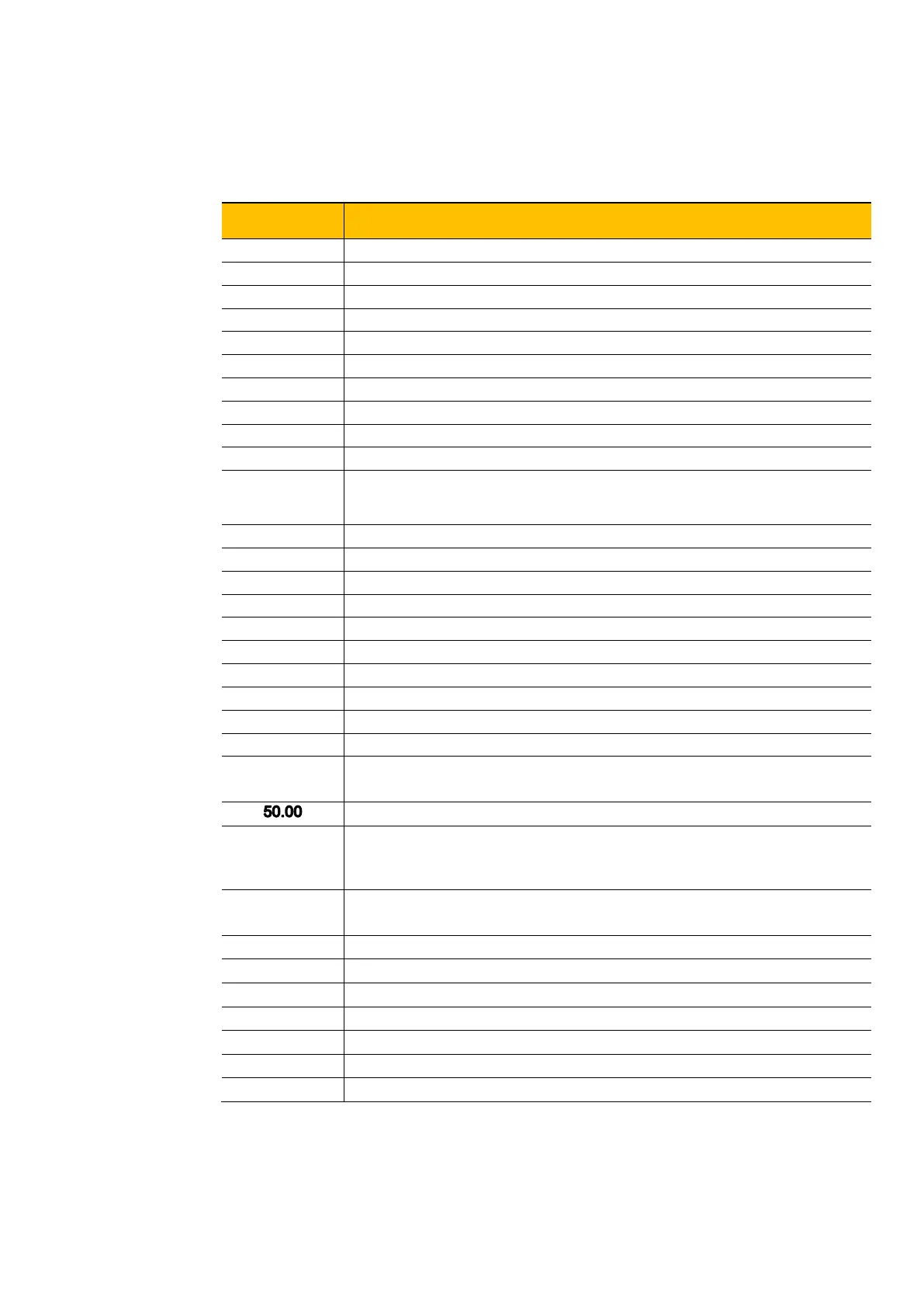
Table 6-4 Items and Remarks Displayed on the Panel
Analog Input has open connection
Indicates Communication error
Tuning parameters are set wrong
Instantaneous Over Current
PID parameters are set wrong
External coast stop terminal is closed, ESP will be displayed.
Indicates Flycatching fault condition
Indicates under-voltage for input condition
This Item will be displayed when you press “M” in stopping status, which
indicates jogging operation is valid. But HF-0 will be displayed only after
you change the value of F132.
It stands for resetting process and will display target frequency after reset.
Indicates over-current condition (OC)
Indicates over-current condition (OC1)
Indicates over-voltage condition
Indicates heatsink over-heat condition
Indicates external over-heat condition
Indicates inverter over-load condition
Indicates motor over-load condition
Indicates phase loss for output condition
Indicates phase loss for input condition
Indicating inverter’s current running frequency (or rotate speed) and
parameter setting values, etc.
Flashing in stopping status to display target frequency.
Holding time when changing the running direction. When “Stop” or “Free
Stop (Coast Stop)” command is executed, the holding time can be
cancelled.
Output current (100A). Keep one digit to the right of the decimal point
when current is below 100A.
PID feedback value is displayed.
Function code (parameter code).
Heat Sink temperature is displayed.
Linear speed is displayed.
PID given value is displayed.

 Loading...


