7-7 Installation & Connection
AC10 Inverter
7.4 Functions of Control Terminals
To operate the inverter the user must operate the control terminals correctly and flexibly. The
following is a description of the user terminals and any relevant parameters.
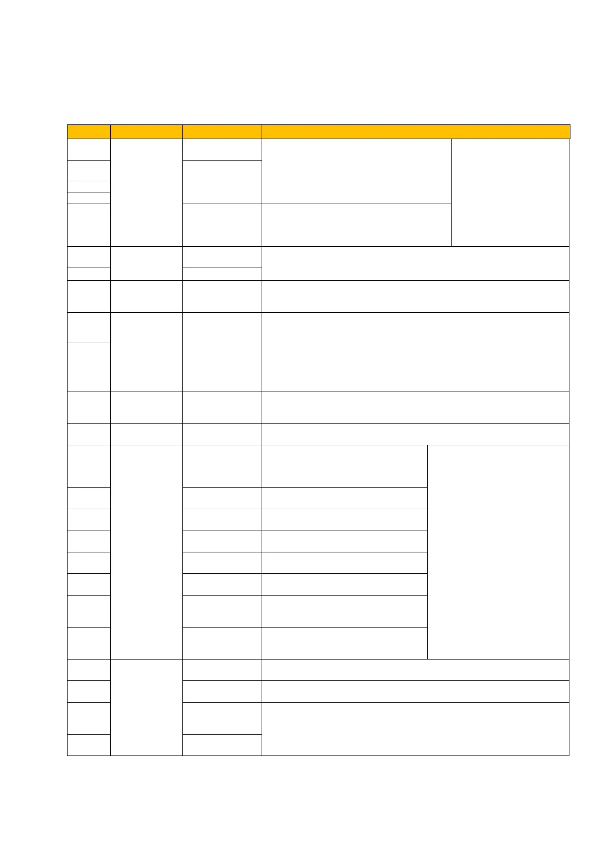
Table 7-3 Functions of Control Terminals
When the function is true, the value between
this terminal and CM is 0V; when the function
is false, the value is 24V. Output current
2mA.
The functions of output
terminals shall be defined
per manufacturer’s value.
Their initial state may be
changed through changing
function codes.
TC is a common point, TB-TC are normally
closed contacts, TA-TC are normally open
contacts. The contact capacity is 10A/125VAC,
5A/250VAC, 5A/30VDC. (See note 3)
It is connected with frequency meter, speedometer or ammeter externally,
and its minus pole is connected with GND. See F423~F426 for details.
Internal 10V self-contained power supply of the inverter provides power to
the inverter. When used externally, it can only be used as the power
supply for voltage control signal, with current restricted below 20mA.
When analog speed control is selected, the voltage or current signal is
input through this terminal. The range of voltage input is 0~10V and the
current input is 0~20mA, the input resistor is 500Ohm, and grounding:
GND. If the input is 4~20mA, it can be realised by setting F406 to 2. The
voltage or current signal can be chosen by coding switch. See Table 8-2
and Table 8-3 for details, the default setting of AI1 is 0~10V, and the
default setting of AI2 is 0-20mA.
Ground terminal of external control signal (voltage control signal or current
source control signal) is also the ground of 10V power supply of this
inverter.
Power: 24±1.5V, grounding is CM; current is restricted below 50mA for
external use.
When this terminal is valid, the inverter
will have jogging running. The jogging
function of this terminal is valid under
both at stopped and running status.
The functions of input terminals
shall be defined per
manufacturer’s value. Other
functions can also be defined by
changing function codes.
When this terminal is valid, “ESP”
malfunction signal will be displayed.
When this terminal is valid, inverter will
run forward.
When this terminal is valid, inverter will
run reverse.
Make this terminal valid under fault
status to reset the inverter.
Make this terminal valid during running
can realize free stop.
When this terminal is in the valid state,
inverter will run by the acceleration
time.
Make this terminal valid during running
can realize stop by the deceleration
time.
Grounding of
differential signal
Ground of differential signal
Power of
differential signal
Power of differential signal
Positive polarity
of differential
signal
Standard: TIA/EIA-485(RS-485)
Communication protocol: Modbus
Communication rate: 1200/2400/4800/9600/19200/38400/57600bps
Note 1: This terminal is not included in 22kW and below 22Kw inverters.
Note 2: GND, 5V, A+, and B- are on separate 4-pole terminal block.
Note 3: The contact capacity for 30kW and above 30kW inverters is 10A/125VAC, NO/NC 3A, 250VAC/30VDC.
Note 4: The “true” state for these terminals is either 24V when configured for PNP operation or 0V when configured for NPN
Operation.

 Loading...


