EasyManua.ls Logo

Parker 10G-46-0600-BF

Parker 10G-46-0600-BF
151 pages
To Next Page IconTo Next Page
To Previous Page IconTo Previous Page
Loading...
8-9 Operation and Simple Running
AC10 Inverter
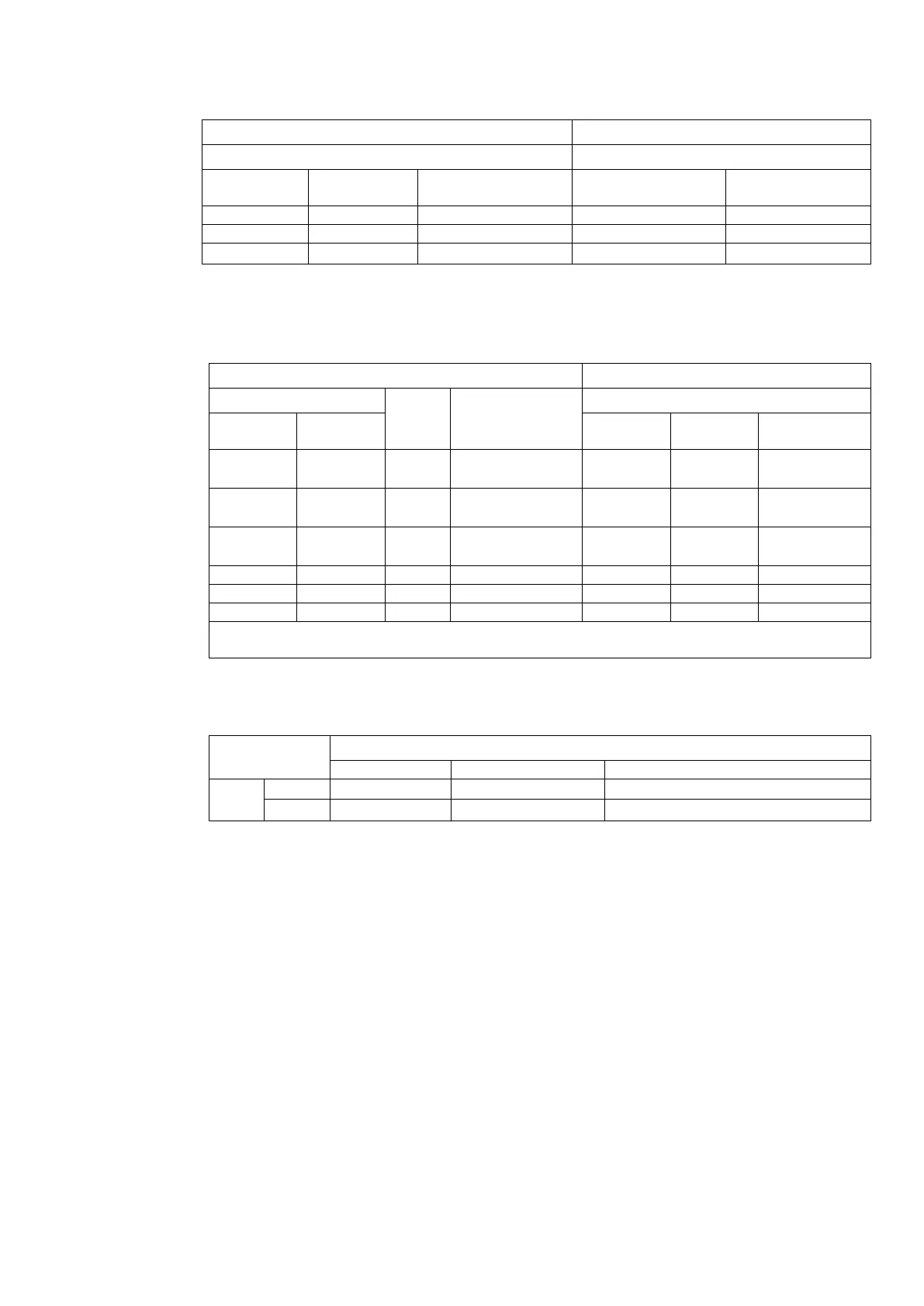
Table 8-2 The Setting of Coding Switch and Parameters for Analog Inputs
F203=2, channel AI2 is selected
F203=1, channel AI1 is selected
SW1 coding switch
S1 toggle switch
Coding
Switch 1
Coding
Switch 2
Analog Input AI2
signal
+
-
OFF
OFF
0~5V voltage
0 ~ 10V voltage
-10 ~ +10V voltage
OFF
ON
0~10V voltage
ON
ON
020mA current
Table 8-3 The Setting of Coding Switch and Parameters for Analog Inputs (in the Mode of
Analog Speed Control).
Set F203 to 1, to select channel AI1
Set F203 to 2, to select channel AI2
Coding Switch SW1
Toggle
switch
S1
Analog signal
range
Coding Switch SW1
Switch 1
Switch 3
Switch 2
Switch 4
Analog
signal range
OFF
OFF
+
05V voltage
OFF
OFF
05V
voltage
OFF
ON
+
010V voltage
OFF
ON
010V
voltage
ON
ON
+
020mA
current
ON
ON
020mA
current
OFF
OFF
-
Reserved
OFF
ON
-
-10~10V voltage
ON
ON
-
Reserved
ON refers to switching the coding switch to the top, OFF refers to switching the coding switch
to the bottom
Table 8-4 The relationship between AO1 and J5 and F423
AO1 output
Setting of F423
0
1
2
J5
V
05V
010V
Reserved
I
Reserved
020mA
420mA

Table of Contents

Related product manuals