Operation and Simple Running 8-8
AC10 Inverter
ii. Press the “M” key, to enter the programming menu.
iii. Study the parameters of the motor: the operation process is the same as that of
example 1. (Refer to 8.3.1 for tuning of the motor).
iv. Set functional parameters of the inverter:
Frames 1 – 5 upto 22kW
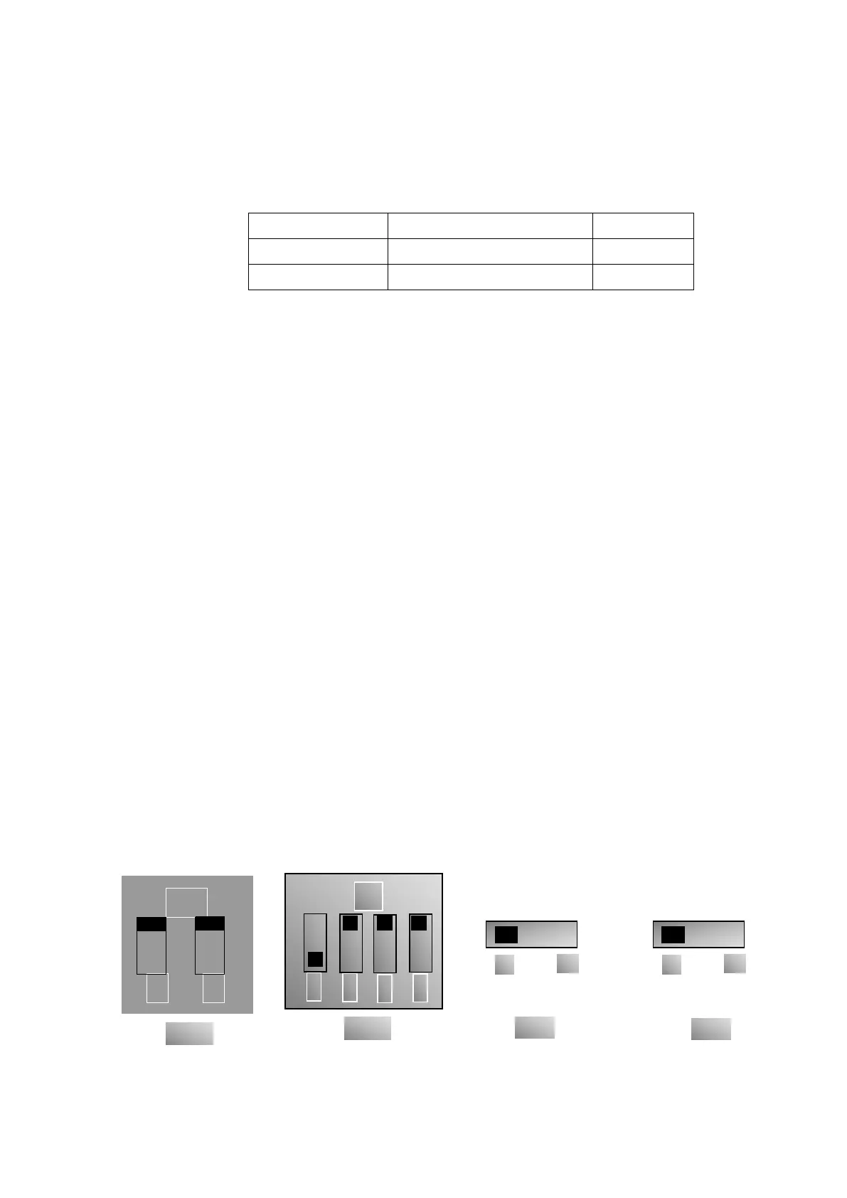
v. There is a red two-digit coding switch SW1 near the control terminal block, as
shown in Figure 8-4. The function of coding switch is to select the voltage signal
(0~5V/0~10V) or current signal of analog input terminal AI2, current channel is
default. In actual application, select the analog input channel through F203. Turn
switches 1 to ON and 2 to ON as illustrated in the figure, to select 0~20mA
current speed control.Other states and modes of these switches are shown in
table 8-2,
Frames 6 – 11 30kW – 150kW
vi. There is a red four-digit coding switch SW1 near the control terminal blockr, as
shown in Figure 8-5. The function of coding switch is to select the input range (0~
5V/0~10V/0~20mA) of analog input terminal AI1 and AI2. In actual application,
select the analog input channel through F203. AI1 channel default value is 0~10V,
AI2 channel default value is 0~20mA. Other states and modes of these switches
are shown in table 8-3.
vii. There is a toggle switch S1 at the side of control terminals,refer to Fig 8-6. S1 is
used to select the voltage input range of AI1 channel. When turning S1 to “+”, the
input range is 0~10V, when turning S1 to “-”, the input range is -10~10V.
viii. Close the switch DI3, the motor starts forward running;
ix. The potentiometer can be adjusted and set during running, and the current setting
frequency of the inverter can be changed;
x. During running process, switch off the switch DI3, then, close DI4, the running
direction of the motor will be changed;
xi. Switch off the switches DI3 and DI4, the motor will decelerate until it stops running;
xii. Switch off the main switch to power off the inverter.
xiii. Analog output terminal AO1 can output voltage and current signal, the selecting
switch is J5, refer to Fig 8-7 the output relation is shown in Table 8-.4.
Figure 8-4 Figure 8-5 Figure 8-6 Figure 8-7
Terminal operational mode

 Loading...


