Installation & Connection 7-4
AC10 Inverter
3-phase 400V 30kW and above
Frame 6 only:
3-phase 230V 15kW
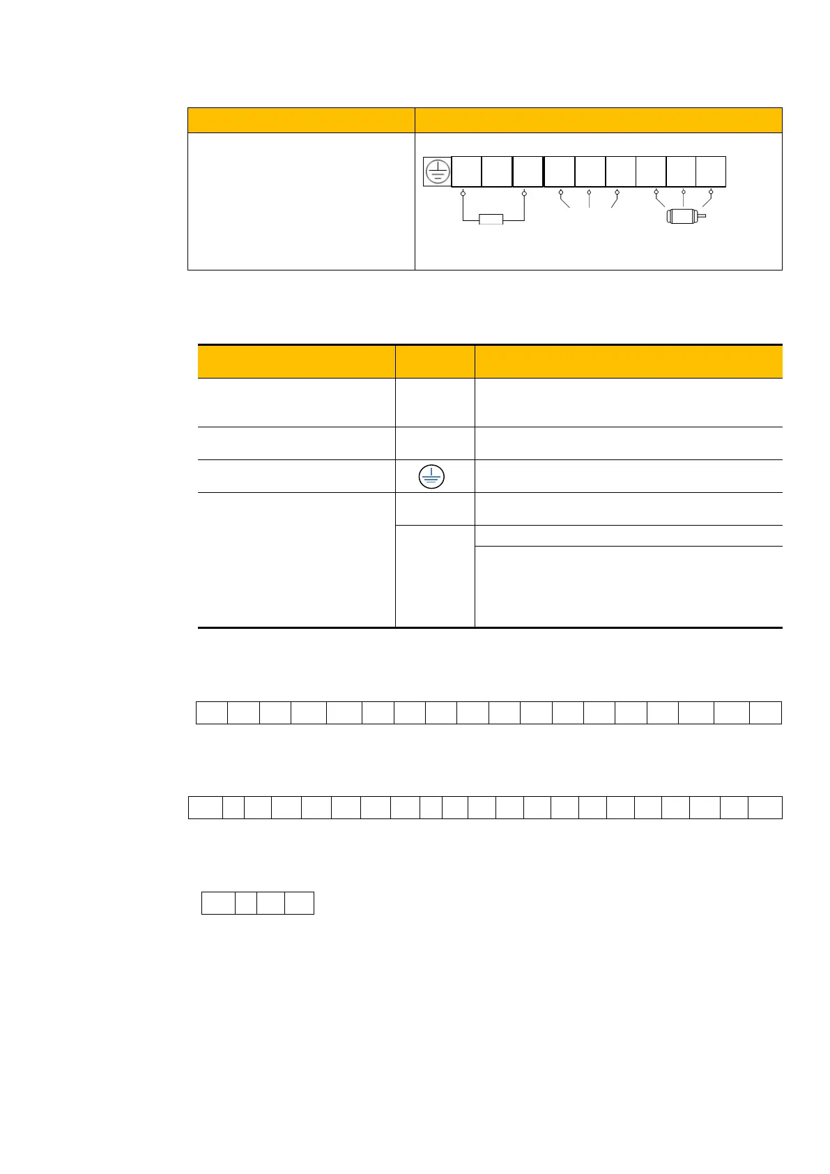
7.2.1 Power Terminals
Terminal Function Description
Input terminals of three-phase 400V AC
voltage (R/L1 and S/L2 terminals for single-
phase)
Inverter power output terminal, connected to
motor.
Inverter grounding terminal.
External braking resistor (Note: no Terminals P
or B for inverter without built-in braking unit).
External connections to optional braking unit
P connected to input terminal “P” or “DC+”of
braking unit,
- connected to input terminal of braking unit “N”
or “DC-”.
7.2.2 Control Terminals
For 22kW and below:
For 30~180kW:
Modbus RTU/RS485
On side of the drive for frames 1 – 5, under front cover for frames 6 - 11

 Loading...


