Function Parameters 9-29
AC10 Inverter
F460 AI1channel input mode
0: straight line mode
1: folding line mode
F461 AI2 channel input mode
0: straight line mode
1: folding line mode
F462 AI1 insertion point A1 voltage value (V)
F463 AI1 insertion point A1 setting value
F464 AI1 insertion point A2 voltage value (V)
F465 AI1 insertion point A2 setting value
F466 AI1 insertion point A3 voltage value (V)
F467 AI1 insertion point A3 setting value
F468 AI2 insertion point B1 voltage value (V)
F469 AI2 insertion point B1 setting value
F470 AI2 insertion point B2 voltage value (V)
F471 AI2 insertion point B2 setting value
F472 AI2 insertion point B3 voltage value (V)
F473 AI2 insertion point B3 setting value
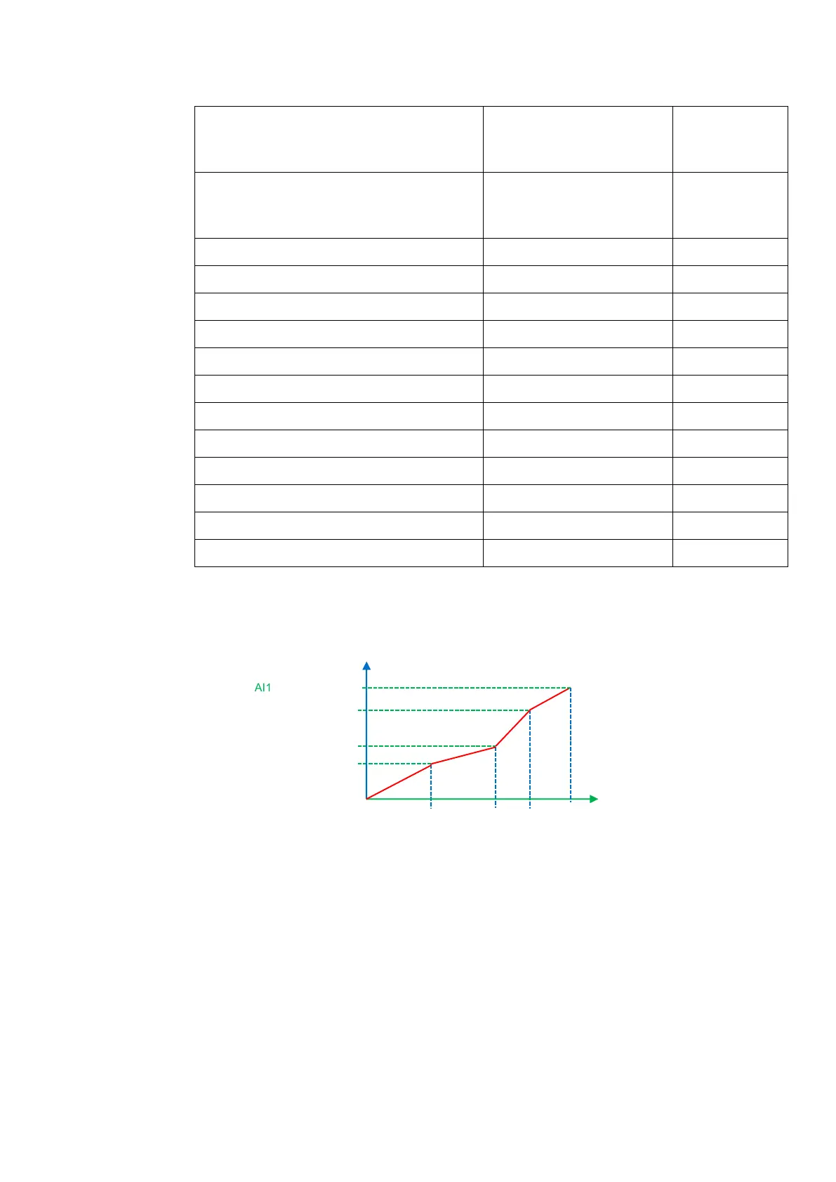
When analog channel input mode selects straight-line, please set it according to the
parameters from F400 to F429. When folding line mode is selected, three points A1(B1,
A2(B2), A3(B3) are inserted into the straight line, each of which can set the according
frequency to input voltage. Please refer to Figure 9-9:
Figure 9-9 Folding analog with setting value
F400 and F402 are lower/upper limit of analog AI1 input. When F460=1,F462=2.00V,
F463=1.4, F111=50, F203=1, F207=0, then A1 point corresponding frequency is (F463-1)
*F111=20Hz, which means 2.00V corresponding to 20Hz. The other points can be set by the
same way.
AI2 channel has the same setting way as AI1.
9.5 Multi-stage Speed Control
The function of multi-stage speed control is equivalent to a built-in PLC in the inverter. This
function can set running time, running direction and running frequency.
AC10 series inverter can achieve 15-stage speed control and 8-stage speed auto circulating.
During the process of Flycatching, multi-stage speed control is invalid. After Flycatching is
finished, inverter will run to target frequency according to the setting value of parameters.
Corresponding Frequency(Hz)
Hz

 Loading...


