8-5 Operation and Simple Running
AC10 Inverter
8.3 Illustration of Basic Operation
Illustration of inverter basic operation: we hereafter show various basic control operation
processes by taking a 7.5kW inverter that drives a 7.5kW three-phase asynchronous AC motor
as an example.
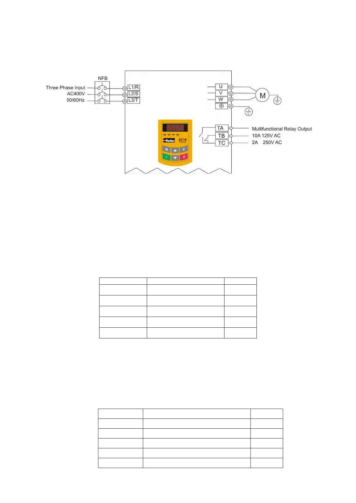
Figure 8-1 Wiring Diagram 1
The parameters indicated on the nameplate of the motor are as follows: 4 poles; rated power,
7.5kW; rated voltage, 400V; rated current, 15.4A; rated frequency 50.00HZ; and rated rotary
speed, 1440rpm.
Frequency setting, start, forward running and stop using the keypad panel
i. Connect the wires in accordance with Table 8-1. After having checked the wiring
successfully, switch on the power to the inverter.
ii. Press the “M” key, to enter the programming menu
iii. Enter the parameters of the motor
Press the “I” key, to autotune the parameters of the motor. After completion of the
tuning, the motor will stop running, and relevant parameters will be stored in
F806~F809. For the details of tuning of motor parameters, please refer to
“Operation process of measuring the motor parameters” in this manual.
Note: F800=1 is rotating tuning, F800=2 is stationary tuning. In the mode of
rotating tuning, make sure to disconnect the motor from the load
iv. Set functional parameters of the inverter:
Mode of direction setting
Main frequency reference source

 Loading...


