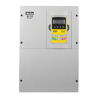
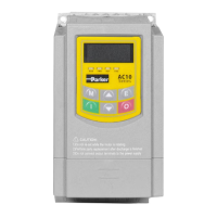
AC10 Inverter
Chapter 1 Introduction .......................................................................................................... 1-1
1.1 Understanding the Product Code ............................................................. 1-1
1.2 Nameplate Example ................................................................................. 1-1
1.3 Product Range .......................................................................................... 1-2
Chapter 2 Product Overview................................................................................................. 2-1
2.1 Designed Standards for Implementation .................................................. 2-1
2.2 Control Features ....................................................................................... 2-2
Chapter 3 Installation ............................................................................................................ 3-1
3.1 Equipment Precautions ............................................................................... 3-1
3.2 Minimum Air Clearance ............................................................................... 3-2
3.3 Inverters Installed in a Control Cabinet .................................................. 3-3
Chapter 4 Maintenance ........................................................................................................ 4-1
4.1 Periodic Checking .................................................................................... 4-1
4.2 Storage ..................................................................................................... 4-1
4.3 Daily Maintenance .................................................................................... 4-1
4.4 Returning the Unit to Parker SSD Drives ................................................. 4-1
Chapter 5 The Keypad .......................................................................................................... 5-1
5.1 The Display .............................................................................................. 5-1
5.2 Remote-control ......................................................................................... 5-1
5.2.1 Panel Mounting Dimensions ............................................................ 5-2
5.2.1 Port of control panel ............................................................................ 5-2
Chapter 6 The Menu Structure ............................................................................................. 6-1
6.1 Parameters Setting ................................................................................... 6-1
6.1.1 Function Codes Switchover in/between Code-Groups ....................... 6-2
6.1.2 Panel Display .................................................................................... 6-3
Chapter 7 Installation & Connection ..................................................................................... 7-1
7.1 Installation ................................................................................................ 7-1
7.2 Connection ............................................................................................... 7-3
7.2.1 Power Terminals ............................................................................... 7-4
7.2.2 Control Terminals .............................................................................. 7-4
7.3 Measurement of Main Circuit Voltages, Currents and Powers ................ 7-5
7.4 Functions of Control Terminals ................................................................. 7-7
7.5 Wiring for Digital Input Terminals: ............................................................ 7-8
7.5.1 Wiring for positive source electrode (NPN mode). ........................... 7-8
7.5.2 Wiring for active source electrode .................................................... 7-8
7.5.3 Wiring for positive Sink electrode (PNP mode) -- Switch J7 set for
PNP. 7-9
7.5.4 Wiring for active drain electrode (PNP mode) (Common Collector
Mode) 7-9
7.6 Connection Overview ............................................................................. 7-10
7.6.1 Terminal Tightening Torques .............................................................. 7-11
7.7 Basic Methods of Suppressing the Noise .............................................. 7-12
7.7.1 Noise propagation paths and suppressing methods ...................... 7-12

 Loading...


