13-11 The Default Applications
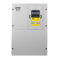
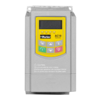
AC10 Inverter
A simple application using a Proportional-Integral-Derivative 3-term controller. The set-point is
taken from AI1, with feedback signal from the process on AI2. The difference between these
two signals is taken as the PID error. The output of the PID block is then used as the drive set-
point.
F203 Main frequency source X
F316 DI1 terminal function setting
F317 DI2 terminal function setting
F318 DI3 terminal function setting
F319 DI4 terminal function setting
F320 DI5 terminal function setting
F431 AO1 analog output signal selecting
FA01 PID adjusting target given source
FA02 PID adjusting feedback given source
1
2
3
5
6
4
7
8
9
10
11
12
13
14
15
16
17
18
TA
TB
TC
1DO
24V
CM
DI1
DI2
DI3
DI4
DI5
10
V
1AI
2AI
GND
1AO
A
B
REF
Stop
Jog
Direction
Run
Feedback
source
not used
not used
Analog output
F431=0 , running
frequency is output
.
GND
Feedback source
AI 2
input
4-20
mA
Speed setpoint
AI1
input
0-10V
10V
Coast stop
Stop
Jog
The jogging direction is
controlled by DI2
.
Direction
inverter runs reverse.
Run
CM
24V
not used
Relay output
Given source

 Loading...


