9-26 Function Parameters
AC10 Inverter
For example: when F400=1, F402=8, if analog input voltage is lower than 1V, system judges it
as 0. If input voltage is higher than 8V, system judges it as 10V (suppose analog channel
selects 0-10V). If Max frequency F111 is set to 50Hz, the output frequency corresponding to 1-
8V is 0-50Hz.
The filtering time constant is set by F405.
The greater the filtering time constant is, the more stable for the analog testing. However, the
precision may decrease to a certain extent. It may require appropriate adjustment according to
actual application.
Channel proportional gain is set by F404.
If 1V corresponds to 10Hz and F404=2, then 1V will correspond to 20Hz.
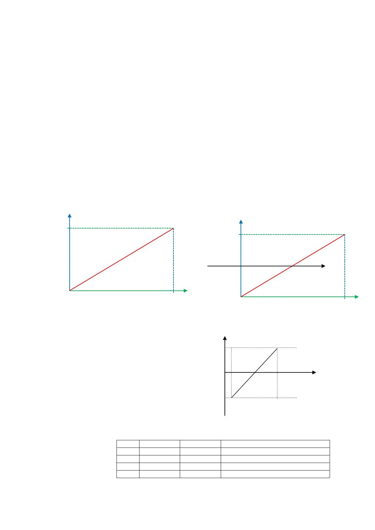
Corresponding setting for upper / lower limit of analog input are set by F401 and F403.
If Max frequency F111 is 50Hz, analog input voltage 0-10V can correspond to output frequency
from -50Hz to 50Hz by setting these group function codes. Please set F401=0 and F403=2,
then 0V corresponds to -50Hz, 5V corresponds to 0Hz and 10V corresponds to 50Hz. The unit
scaling the upper / lower limit of input is in percentage (%). If the value is greater than 1.00, it
is positive; if the value is less than 1.00, it is negative. (e.g. F401=0.5 represents –50%).
If the running direction is set to forward running by F202, then 0-5V corresponding to the
minus frequency will cause reverse running, or vice versa.
Figure 9-8 Correspondence of analog input to setting
The unit of for scaling the upper / lower
limit of input is in percentage (%). If the
value is greater than 1.00, it is positive; if
the value is less than 1.00, it is negative.
(e.g. F401=0.5 represents –50%).
The corresponding setting benchmark: in
the mode of combined speed control,
analog is the secondary frequency and
the setting benchmark for range of
secondary frequency which relatives to
main frequency is “main frequency X”;
corresponding setting benchmark for other cases is the “max frequency”, as illustrated in the
above figure.
Should be max frequency (F111)
Should be max frequency (F111)
Low limit of Aix channel input (V)
Upper limit of Aix channel input (V)
Corresponding Frequency (Hz)
0V
Corresponding Frequency (Hz)
0V

 Loading...


