Quantum GX2 microCT Imaging System Manual Chapter 3 | Quantum GX2 microCT Imaging System Components 19
Control Panel
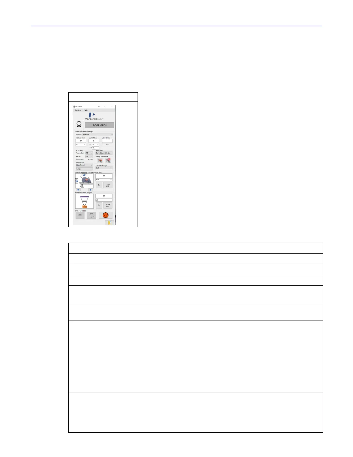
The Control Panel appears when the Quantum GX2 microCT software starts (Figure 3.6). See:
Page 26 for instructions on starting the software and Control Panel details.
Page Table 4.2 on page 27 for details on the Control Panel.
Figure 3.6 Control Panel
Table 3.2 Scan Acquisition and Display Parameters
Parameter Description
Voltage Variable voltage up to 90 kV.
CT Variable current up to 200 µA.
Live Variable current up to 500 µA.
FOV (mm) Acquisition – Field of view for acquisition, variable 18 - 86 mm.
Reconstruction – Field of view for reconstruction, variable.
Voxel Size Voxel size determined by the software based on the acquisition FOV and
reconstruction FOV.
Scan Mode
Standard – A common scan configuration for low dose in vivo imaging.
High Resolution – A scan mode that reduces image noise.
High Speed, Whole Body – A scan configuration that performs multiple scans and
stitches them together to increase the axial field of view. After the first scan, the bed
moves into the bore and the next scan is completed. The software uses the images
from all of the scans to generate the 3D reconstruction (.vox).
High Speed – A scan mode that is as fast as possible to reduce dose.
High Speed, Gating – A scan configuration which mitigates motion artifacts from
cardiac and respiratory rhythms. Note: Gating is optional.
Note: See Table 6.2 on page 44 for details on Preset Scan Configurations.
Display Settings 3D filters remove noise by combining pixels and displaying the average intensity of
the selected pixels:
Original – Does not apply a filter.
Soft – Applies a 3 x 3 x 3 averaging filter.
Smooth – Applies a 5 x 5 x 5 averaging filter.
 Loading...