13 - 2
Adjustment
49-020
1
5
4
6
3
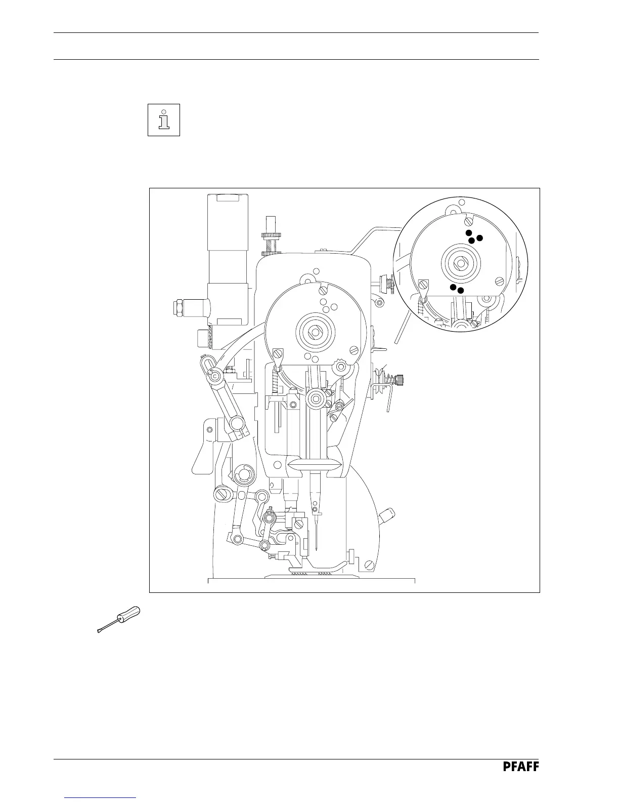
13.04 Control and adjustment aids
By marking the holes 1
and 3 - 6
with the adjustment pin (ø 5 mm), the desired
needle bar positions can be fixed exactly.
● Turn the balance wheel until the needle bar is approximately in the desired position.
● Insert the adjustment pin into the appropriate hole and apply pressure.
● Turn the balance wheel slightly backwards and forwards, until the pin locks into the rear
crank recess, in this way blocking the machine.
Adjustment hole 1 = 0.6 mm past top dead centre of the needle bar (0.6 past t.d.c.)
Adjustment hole 3 = 0.6 mm past bottom dead centre of the needle bar (0.6 past b.d.c.)
Adjustment hole 4 = 1.8 mm past bottom dead centre of the needle bar (1.8 past b.d.c.)
Adjustment hole 5 = top dead centre of the needle bar (t.d.c.)
Adjustment hole 6 = 4.0 mm past bottom dead centre of the needle bar (4.0 past b.d.c.)
Fig. 13 - 01
49-020f
1
5
4
6
3
 Loading...


