13 - 35
Adjustment
2
4
V
=
4
%
E
D
49-086
49-085
Fig. 13 - 34
2
3
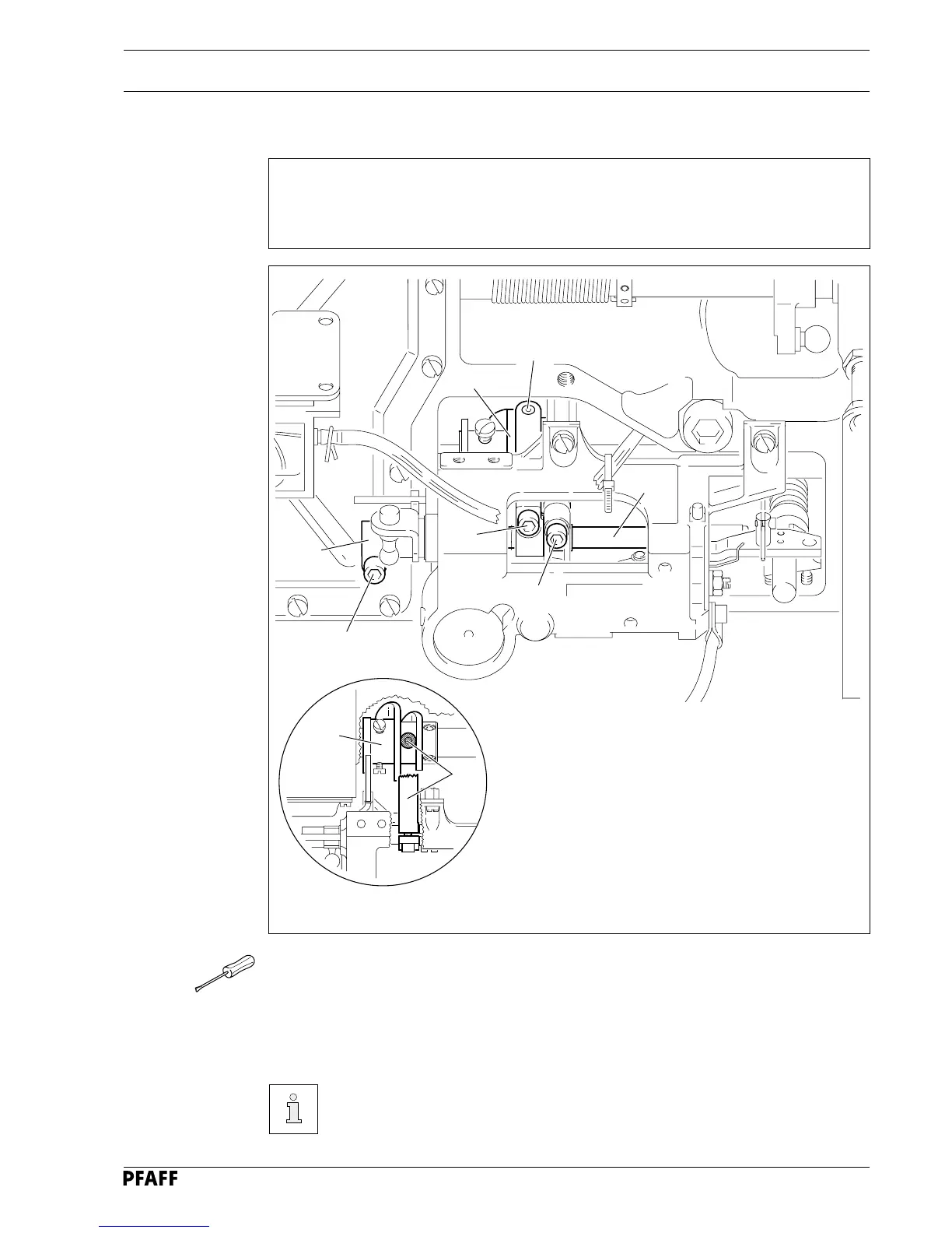
13.06.02 Roller lever
Requirements
When the needle bar is positioned 1.8 mm after the b.d.c,
1. the roller of the roller lever 4 should engage easily with the control cam 7 and
2. the roller of roller lever 4 should be centred in the cam notch of the control cam 7
4
7
5
6
1
4
7
● Unscrew screws 1 and 2.
● Put pressure on rockshaft
33
33
3 to the right.
● Adjust roller lever 4 in accordance with requirements 1 and 2.
● Tighten screw 1 firmly.
● Position the surface of the fixing collar 5 (bolt 6) parallel to the base plate.
Screw 2 stays undone for the following adjustment.
 Loading...


