Display of the test results
Test result Display
Control panel
Leak rate below the warning point or the reject point if the warning point is disa-
bled
Screen: green
Bargraph: white
Graph: white line
Leak rate between warning point and reject point Screen: green
Bargraph: orange
Graph: orange line
Leak rate greater than the reject point Screen: red
Bargraph: white
Graph: red line
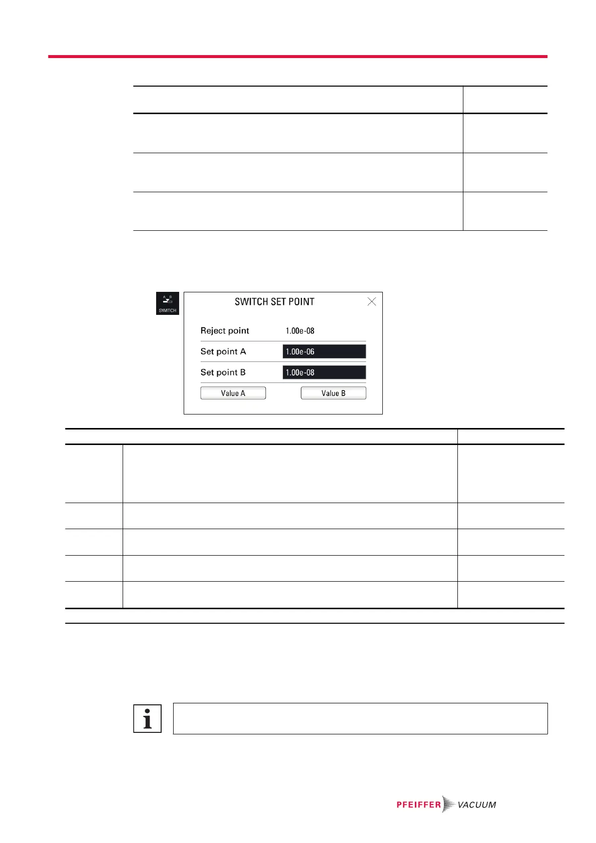
Switch set point function
The Switch set point function is used to store 2 reject points and then assign one to the hard vacuum
test or sniffer reject point (depending on the test method set).
►
Allocate a function key to [SWITCH SETPOINT] (see “Function keys”).
Access: [SWITCH SETPOINT]
Choice - Setting limit
1)
Reject point Read only
Set reject point
● hard vacuum test set point or sniffer set point depending on the test method
set
● Set point for the tracer gas selected
-
Set point A To be set
Reject point A is an acceptance set point for parts.
1 · 10
-13
– 1 · 10
+06
Set point B To be set
Reject point B is an acceptance set point for parts.
1 · 10
-13
– 1 · 10
+06
Value A Function launching
Allocation of the reject point value A to the reject point
-
Value B Function launching
Allocation of the reject point value B to the reject point
-
1) Initial setting: see chapter “Tree diagram to the Settings menu”
8.1.3 Correction factor
The correction factor is used to correct the leak rate measured by the leak detector when the tracer gas
concentration is less than 100%.
A light indicating that the function is enabled is displayed on the main screen.
Use of the correction factor must not replace calibration.
Settings menu
49/98