6. If the value of the correction factor to be applied is known:
a
Press [Value].
b
Set the correction factor to be applied. The correction factor is the coefficient to be applied to
the measured leak rate.
C
Press [✔].
C
Press [X].
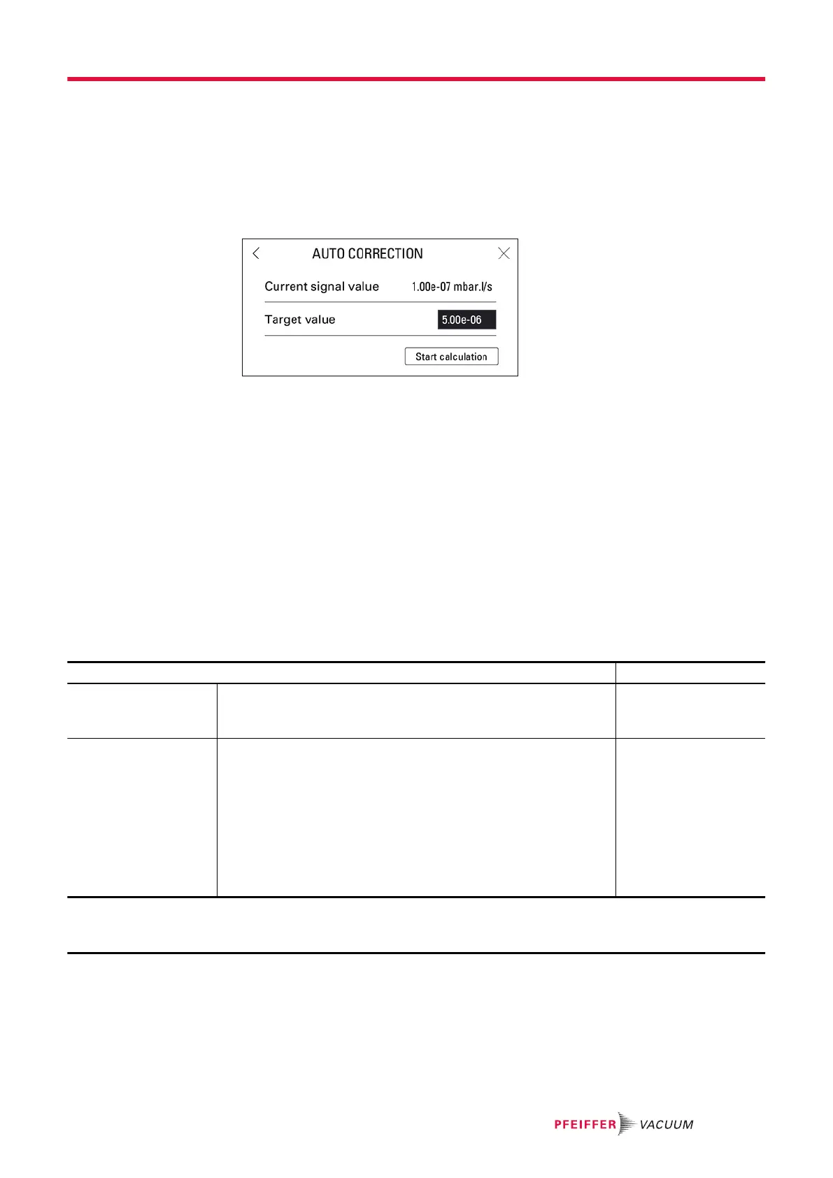
7. If the value of the correction factor is unknown:
a
Press [>>] to access the ‘Auto Correction’ function.
b
Press [Target Value].
C
Set the target leak rate of the target value.
d
Press [Start Calculation].
e
Press [X] to exit the function.
8. if no factor is enabled, it is 1 by default
The value of the correction factor is calculated automatically and updated.
The COR indicator light is displayed on the control panel when the value of the correction factor is not 1.
The ‘Auto correction’ function is automatically enabled.
The digital display takes into account the applied correction factor.
The bargraph display does not take into account the applied correction factor.
8.1.4 Calibrated leak settings
This menu is used to enter and view the settings of the calibrated leaks (see chapter “Calibration”).
►
Update these settings when changing or recalibrating a calibrated leak.
Access: Menu [Measurement] [Calibrated leak settings]
Choice - Setting limit
1)
Tracer gas To be selected
The tracer gas is the gas searched for during a test.
This is the gas contained in the calibrated leak used for calibration.
Helium 4
Mass 3
Hydrogen
Type To be selected
Type of calibrated leak used for calibration
● Internal: calibration based on the detector’s internal calibrated
leak
‘Hard vacuum’ test method only
●
External: calibration based on external calibrated leak (
4
He,
Mass 3 or H
2
leak).
● Concentration: calibration from a gas mixture for which the trac-
er gas concentration is known.
Sniffer test method only
Internal
External
Concentration
1) Initial setting: see chapter “Tree diagram to the Settings menu”
2) Use the information indicated on the calibrated leak used for calibration or on its calibration certificate.
3) If sniffer test method selected
Settings menu
51/98