Mechanical Instructions
EN 11BJ3.0E PA 4.
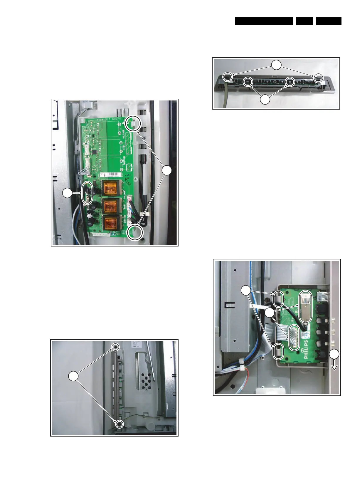
4.3.5 AmbiLight Inverter Panel
There are two AmbiLight Inverter Panels used in this set. The
instructions to remove the right one (seen from the back side of
the set) are as follows:
1. Disconnect the cables [1] from the panel.
2. Push back the clamps [2] on the right side that hold the
assy.
3. Take out the panel (it hinges on the left side).
When defective, replace the whole unit.
Figure 4-7 AmbiLight right side inverter panel removal
4.3.6 Control Panel
The Control Panel can be taken out by removing the two T10
screws [1] that hold the plastic frame. See Figure “Control
panel removal”. The cable can not be disconnected from the
assy at this moment. While still connected to the assy, the
cable must now be released from the two clamps on the
chassis nearest to the assy.
Figure 4-8 Control panel removal
The assy is packed into two plastic frames. To unpack the
inner frame, lift the two clamps [1] of the outer frame and take
the inner frame out. See Figure “Control panel frame removal”.
Figure 4-9 Control panel frame removal
To take the assy out of the inner frame, lift the two clamps of
the frame [2] and slightly pull the assy out. Only now the cable
can be disconnected.
When defective, replace the whole unit.
4.3.7 Side I/O Panel
The Side I/O Panel can be removed together with its plastic
frame.
1. Disconnect the USB cable and the flat cable [1] from the
panel.
2. Push the plastic frame slightly downwards towards the
bottom of the set [2], and take the frame out together with
the assy.
3. Push back the clamps [3] on the left side that hold the assy.
4. Take out the assy from the plastic frame, it hinges on the
right side.
When defective, replace the whole unit.
Figure 4-10 Side I/O panel removal
4.3.8 Audio Panel
1. Disconnect all cables from the Audio Panel.
2. Remove the two T10 mounting screws [1] from the Audio
Panel. See Figure “Audio Panel removal”.
3. Take out the Audio Panel (it hinges at the right side).
G_15960_110.eps
070306
11
42
G_15960_099.eps
070306
11
G_15960_100.eps
070306
11
12
G_15960_098.eps
100306
41
22
3