Service Modes, Error Codes, and Fault Finding
EN 33BJ3.0E PA 5.
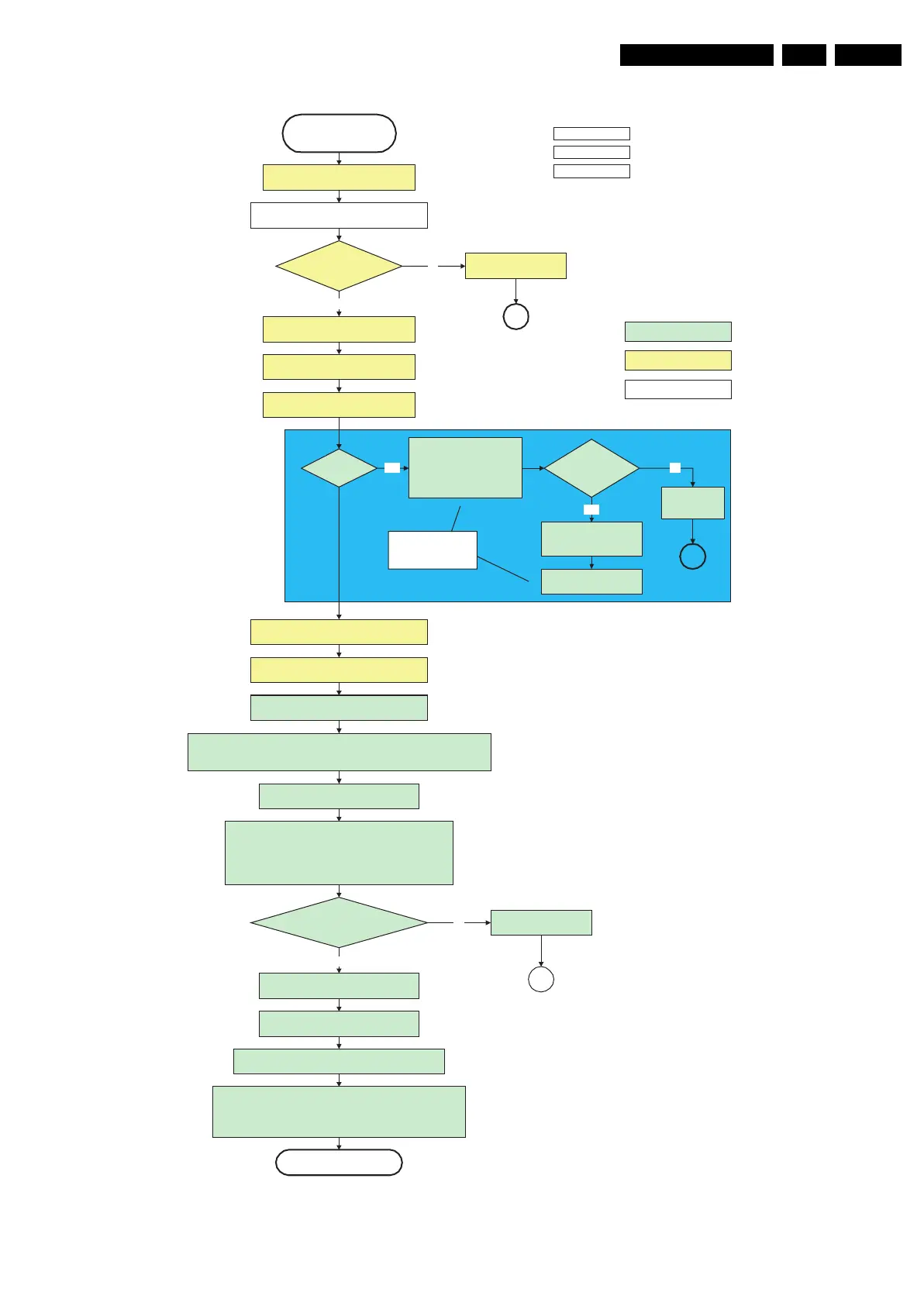
Figure 5-14 “POD Stand-by” to “Semi stand-by” flowchart
G_15960_135.eps
100306
action holder: MIPS
autonomous action
action holder: St-by
action holder: MIPS
autonomous action
action holder: St-by
Semi-Standby
MPIF's should be initialized according the FMS information.
MPIF should deliver 4 observers:
POR= 0; normal operation
MSUP = 1: Main supply is present
ASUP = 1; audio supply is present
ROK = 1; reference frequency is present (coming from AVIP)
(AVIP's need to be started before the MPIF's in order to have a good clock distribution).
AVIP default power-up mode is Standby. The Viper instructs AVIP via I²C to enable all the
PLL's and clocks and hence enter to Full Power mode. See FMS AVIP for further details
and the rest of the initialization.
initialize tuners and Hirate according FMS
information
All observers present with correct state? appropriate Observer errorNo
Yes
Initialize video processing IC's according FMS information:
- Spider
Initialize source selection according FMS
and CHS information
initialize Columbus by triggering CHS Columbus Init interface
initialize 3D Combfilter by triggering CHS 3D Comb filter Init interface
initialize AutoTV by triggering CHS AutoTV Init interface
See appropriate CHS documents for further details.
MP
POD stand by
initialize PNX2015 HD subsystem according
FMS information
Full SSB power and the display related supplies
become available
Switch ON all supplies by switching LOW
the ON-MODE I/O line.
+8V6 error
+8V6
detected within
2000 ms after ON-MODE
toggle?
No
Yes
SP
activate +8V6 supply
detection algorithm
SDI PDP
Set?
Yes
Log display
error and enter
protection mode
Switch ON the LVDS output of
the PNX2015 with a correct
clock frequency within 4s after
switching the POD and ON-
mode to prevent PDP display
supply protection.
Init SDI P DP by tr ig ge ring
CHS displays'
Initialize_display interface
Yes
PWR-OK-PDP
received within 5s
after POD and ONmode
toggle ?
No
SP
Switch LVDS back off if
end state is not the active
state.
These LVDS items are
SDI V3 display only !!
Wait 2000ms to allow main supply to
deliver full power.
Power-up HDMI and 1394 hardware by putting
POWERDOWN-1394 GPIO 0 line low.
Enable Viper HW blocks (TM1, TM2, MBS, VMSP1 and
VMSP2) which were in powerdown mode.
Release PNX2015 reset
Enable audio protection algorithm