Service Modes, Error Codes, and Fault Finding
EN 34 BJ3.0E PA5.
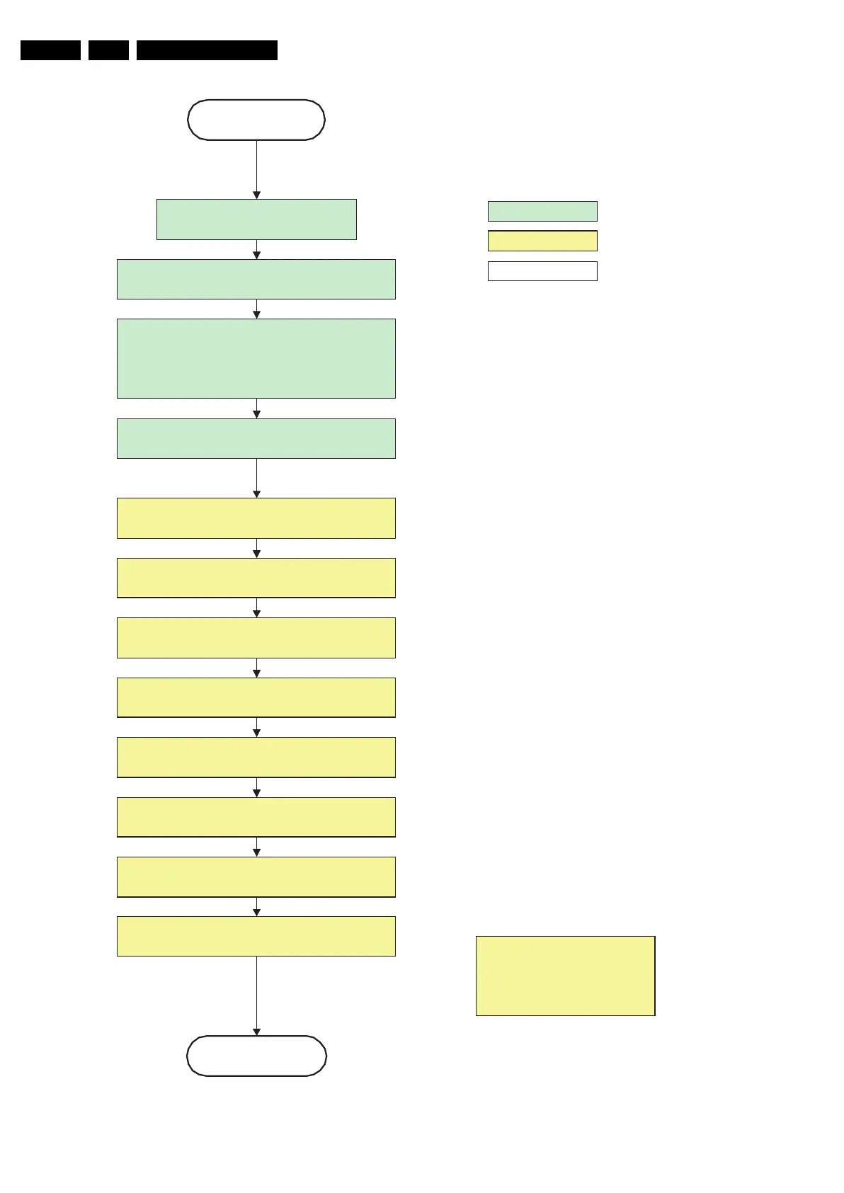
Figure 5-15 “POD” to “Stand-by” flowchart
G_15960_136.eps
100306
action holder: MIPS
autonomous action
action holder: St-by
transfer Wake up reasons to the
Stand by µP.
Images are re-transferred to DDR-RAM from
Flash RAM (verification through checksum)
Stand by
POD
MIPS image completes the application reload,
stops DDR-RAM access, puts itself in a
sleepmode and signals the standby µP when the
standby mode can be entered.
Disable all supply related protections and switch off
the +2V5, +3V3 DC/DC converter.
DDR-RAM is put in self refresh mode and the images
are kept in the hibernating DDR-RAM.
Switch OFF all supplies by switching HIGH the POD-
MODE I/O line.
Switch Viper in reset state
Important remark:
release reset audio and sound-
enable 2 sec after entering
standby to save power
switch off the remaining DC/DC converters
Wait 5ms
Wait 5ms
Wait 10ms
Switch the NVM reset line HIGH.