Phoenix LT4 Lane Machine Operation, Maintenance, and Parts Manual
61-900040-000 Rev. Date 01/22
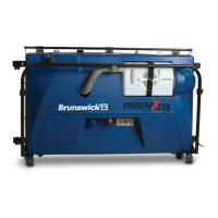
Buffer Motor Assembly
SCREW, SET, CUP POINT 1/4-20 X 1/4
BUFFER MOTOR ASM, 110V (INC. 2,3,4, & 5)
BUFFER MOTOR ASM, 220V (INC. 2,3,4, & 5)
BUFFER MOTOR PIGTAIL (INC. 4 & 5)
CRIMP TERMINAL, FEMALE, 14-20 AWG
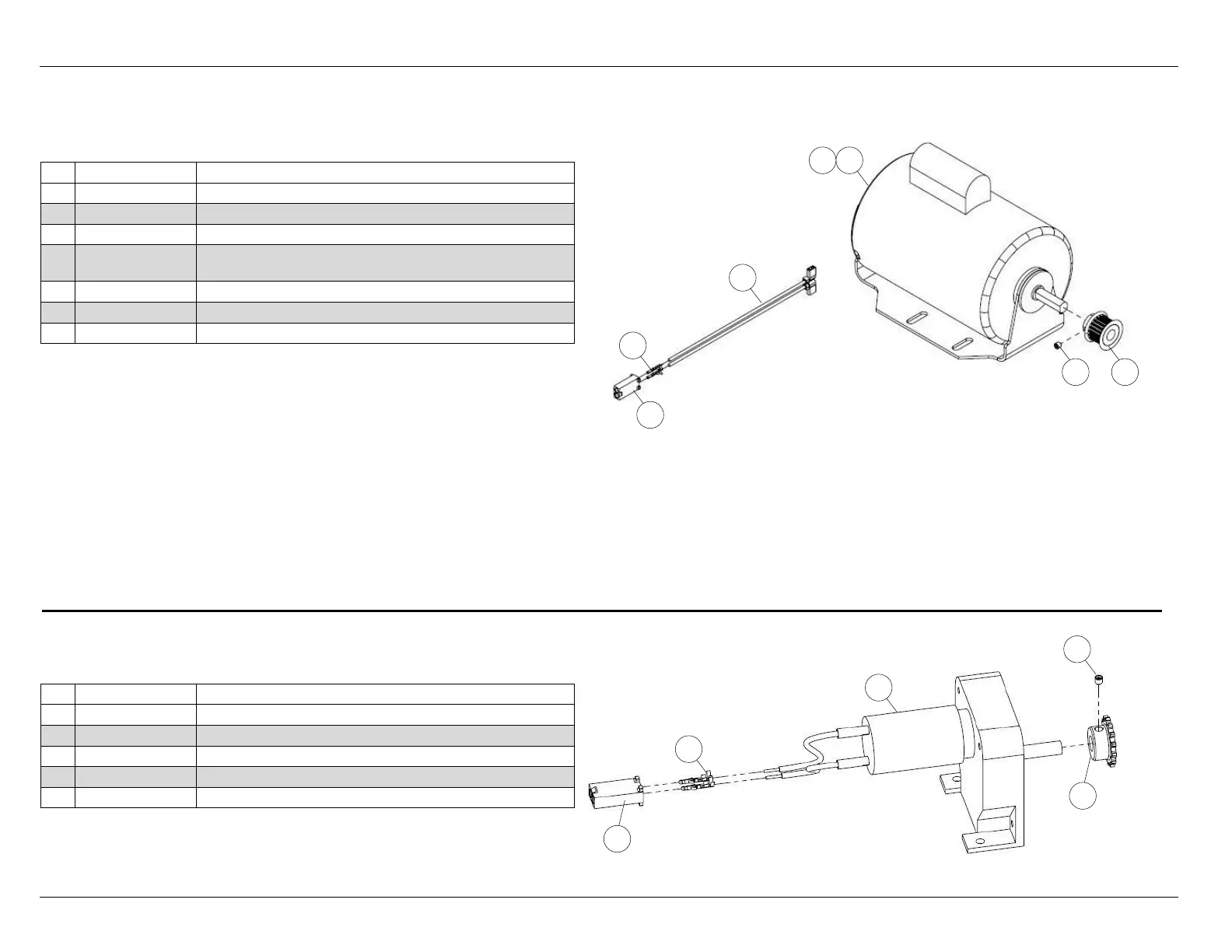
Transfer Roller Motor Assembly - 294-116-150
SCREW, SET, CUP POINT 10-32 X 3/16
TRANSFER MOTOR ASM (INC. 4 & 5)
CRIMP TERMINAL, MALE, 14-20 AWG
The buffer motor must be wired for either 110V or 220V use.
Remove motor endcap cover for wiring access. For both 110V
and 220V operation, connect pigtail blue wire to L1 and pigtail
black wire to L2 then follow the instructions below.
For 110V operation connect: the red wire to the #2 terminal
and the black wire to the #4 terminal.
For 220V operation connect: the red wire to the #2 terminal,
white wire to the #3 terminal, black wire to the #4 terminal, and
blue to the #5 terminal.