Operation
61-900040-000 Rev. Date: 01/22 3-17
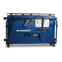
The hook-and-loop straps hold the power cord up and away from the moving parts of the
machine and help prevent it from dragging on the lane as the machine moves (see Figure
3- 36). It also relieves stress on the power cord as it is pulled when the machine moves.
The recommended power cord path is:
1. Plug the power cord into the machine.
2. Clip the power cord’s strain relief into the
hook located on either side of the Phoenix
LT4 frame.
3. Run the power cord along handle and secure
it with the hook and loop strap.
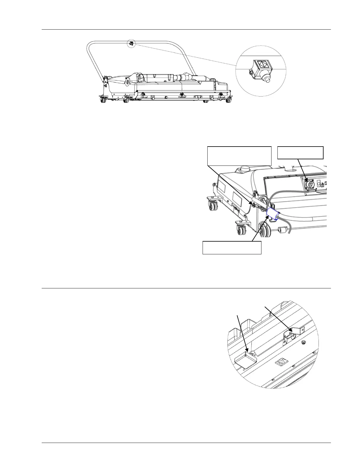
3.5 OPTICAL SENSOR
The Phoenix LT4 Lane Machine is equipped with an
optical sensor that detects the end of the lane (EOL).
When looking at the front of the machine, the sensor is
located to the right of the middle sprayer head and is
protected by a metal cover as shown in Figure 3- 37.
It is positioned so that it “looks” down on the lane.
Information from this sensor is used only when the
machine is traveling from the approach to the pin deck.
The sensor is continually testing for a change in height.
When the sensor detects the end of the lane, it sends a
signal to the controller that initiates the braking routine.
This prevents the machine from running into the pit.
Front Optical
Sensor and Cover
3. Secure it with the
hook-and-loop strap.
1. Plug in the blue
connector.
2. Clip the strain relief to
the spring hook on the
side of the machine.